


As designers are challenged to integrate an increasing number of sensors in products, aggregating different data streams from dissimilar sensors (e.g., imaging cameras, lidar, radar) is the new normal for input/output-(I/O) constrained application processors. A central challenge across many use cases—such as drones, AR/VR, and automotive—is how to get multiple data streams into the I/O-constrained system-on-chip (SoC) processor.
Traditional inertial sensors (accelerometers, galvanometers, etc.) provide relative positioning, which accumulate errors overtime. Therefore, designers are migrating to environment-aware cameras, in an AR headset camera for example, to tie in stationary objects as external references providing absolute positioning. Mathematically significant points become markers in the camera image to generate relative position to fixed points. An example of a marker might be a table corner or floor pattern, as thousands of points are integrated into an augmented world.
An example that illustrates this central challenge is an industrial inspection station for qualifying printed circuit boards (PCBs), which has multiple cameras. One camera monitors the whole PCB, and several other cameras focus on different regions. The camera subsystem sends multiple video streams to the SoC.
If these cameras are identical, they may be combined through synchronization and signal concatenation—two or more cameras and their video streams are synchronized. In the case of two cameras, the output image transported to the SoC simply has twice the aspect ratio of the input.
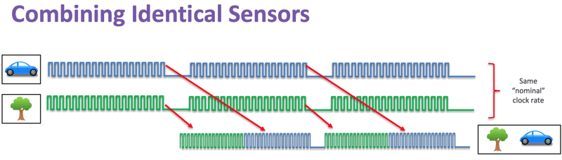
Figure 1: To combine streaming data from identical sensors cameras, you can synchronize the cameras, buffer the lines and concatenate both lines at twice the frequency. (Image: Lattice Semiconductor)
Dissimilar cameras, however, may have different frame rates, resolutions and bandwidths. In Figure 2 below, the upper image is a statue at a higher resolution in the visual spectrum. The bottom image is an IR heat map at a lower resolution. The different data stream frequencies and block lengths pose challenges, but with a few SoC I/O pins, you can assemble video streams as they come in, concatenate them and send them out as a virtual video stream.
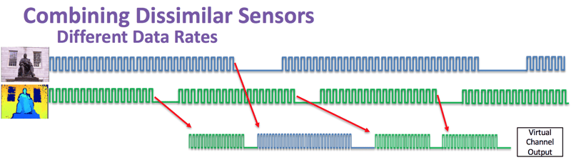
Figure 2: Dissimilar sensors with different data rates cannot be synchronized and run in different clock domains. (Image: Lattice Semiconductor)
MIPI Camera Serial Interface 2 (MIPI CSI-2SM) offers a solution for allowing differing data streams from dissimilar sensors into a pin-constrained SoC by providing several virtual channels (VCs) in a single stream. The VC’s packetized format includes a header, payload data and footer. In the header, a variety of fields could include data length, data type and a field for the VCs. The latest version, MIPI CSI-2 v3.0, for instance, is backward compatible and provides up to 32 VCs in one stream. It can be implemented on either MIPI C-PHYSM v2.0 or MIPI D-PHYSM v2.5.
Using VCs, you can map several video sources to one output. Four or fewer channels coming into your application processor is relatively easy, as you can map that data to one output video stream. There are a couple of techniques for mapping more than four input channels, such as concatenating identical streams and treating them as one VC. Another possibility—the header data contains a field called data type, and you can use it to extend your VC field.
Another challenge for integrating dissimilar sensors is in the hardware logic requiring multiple clock domains, where data is received at different phases and frequencies from one another. This creates a challenge of meta-stability in digital circuits.
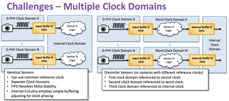 Figure 3: Identical sensors on the left, for example, cameras—can use a common clock reference but need separate clock domains. (Image: Lattice Semiconductor)
For example, if you have two identical cameras running at the same clock speed coming into your system, you can easily aggregate them. However, each receiver needs to be running in its own clock domain. Even if the receivers are running at the same frequency, each receiver needs a separate clock domain to avoid meta-stability issues due to phase difference. These transceivers will typically work at the bit level. Once you translate bit-level data into word-level data, you move data to another block domain into your output transmitter. The difficulty shown in Figure 3 (above) is moving data between these clock domains—if not treated appropriately, you can lose or corrupt data. A clean way to move data across clock domains is with a dual-port RAM configured as first in, first out (FIFO). FIFOs, by design, will get the data across your clock domains.
Two dissimilar image sources are shown in Figure 3. Each source must have its own domain with bit-level data coming in and crossing another clock domain to work with word-level data. Since the word-level data in Figure 3 runs at a different frequency, you are still in a different clock domain. Next, you translate the word data into the transmitter domain and send it out. In Figure 3, there are four transitions between five different clock domains—for two cameras. A well-designed FIFO can handle the data transitions between blocks, leaving you as the designer to focus on higher architectural issues.
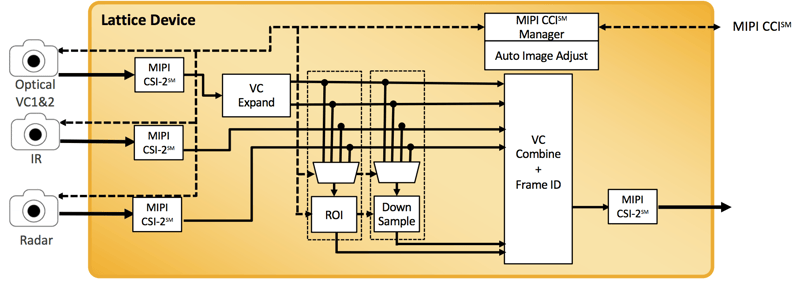 Figure 4: Virtual channel preprocessing in hardware involves balancing power and performance. (Image: Lattice Semiconductor)
One last topic of discussion is, now that we have methods for these disparate data streams to interface with the application processor, how do we balance the load? Figure 4 depicts the pain points of the application processor to handle compute-intensive data streams. MIPI Camera Command Interface (CCI) helps with this problem. CCI allows you to regulate camera parameters such as resolution and frame rate as a dynamic application may require.
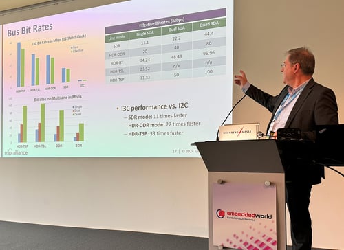
Host processors may use CCI, a bidirectional and two-wire interface to configure and control cameras before, during or after image streaming using the high-speed MIPI D-PHY or MIPI C-PHY interfaces. Implementations of CCI can use I2C Fast Mode+ (FM+), which supports up to 1 Mbps. But additionally, the interface delivers data at 12.5 Mbps when used with MIPI I3C® Single Data Rate (SDR) mode. When used with MIPI I3C's High Data Rate (HDR) Double Data Rate (DDR) mode, it delivers 25 Mbps.
This article was based upon Lattice Semiconductor Corp.'s MIPI DevCon Seoul presentation “Integrating Image, Radar, IR and TOF Sensors: Developing Vision Systems with Dissimilar Sensors.” Consider helping shape future versions of MIPI CSI-2 by joining the MIPI Camera Working Group.