


Updated September 2023
MIPI White Paper:
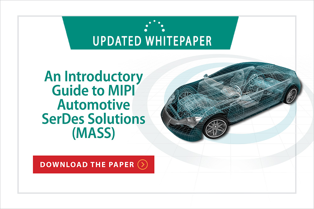
An Introductory Guide to MIPI Automotive SerDes Solutions (MASS)
An overview of MIPI’s standardized in-vehicle connectivity framework for high-performance sensors and displays
This introductory guide explains how MIPI Alliance is addressing automotive requirements with MIPI Automotive SerDes Solutions (MASS), an end-to-end, full stack of connectivity solutions for the growing number of cameras, sensors and displays that enable automotive applications. It outlines how these solutions, with unprecedented functional safety and security built in at the protocol level, will help automakers integrate new and emerging safety features using the latest camera, lidar and radar systems. It also describes how MASS supports the integration of multiple high-resolution instrumentation, control and entertainment displays.
In addition, the white paper includes a detailed technical overview of the MASS framework, explaining how the four principal components of MASS (physical layer interface, higher-layer protocols, functional safety and security) combine to create an end-to-end automotive connectivity framework.
First published in August 2021, this white paper was recently updated to reflect the most recent developments to MASS specifications to ensure the framework addresses the latest and most advanced automotive use cases.
The 2023 refresh includes the current specifications that make up the MASS framework, as well as key updates such as:
- An overview of how the MIPI Security Framework can be applied to MASS, with specific focus on how new security functionality in forthcoming specifications will provide application-level “end-to-end” data protection regardless of the underlying network topology
- A preview of future MIPI A-PHY® developments, including A-PHY v2.0 and the MIPI Power Over A-PHY (PoA℠) specification
- New example use case showing how MASS enables daisy-chaining of multiple high-resolution automotive displays, reducing the complexity and weight of cable harnesses and simplifying the connection of the displays during vehicle manufacturing
Read the White Paper
To download the white paper, please submit the form on this page. You'll receive a download link on the response page.