


Legacy protocols for board-level communication are no longer sufficient for the new requirements presented by the electronics industry after its recent years of significant evolution. MIPI I3C® is an interface that closes the gaps and addresses the need for higher speed and more efficient data transfer with low power and low-wire-count communication systems.
MIPI I3C and its publicly available subset, I3C Basic℠, which bundles the features most commonly needed by developers and other standards organizations, brings an unparalleled advantage to sensor-node implementations in a range of mobile, Internet of Things (IoT) and automotive applications, compared with the legacy serial communication protocols that are mainly used in sensor nodes. The comparison table in the original MIPI Alliance I3C white paper, "Introduction to the MIPI I3C Standardized Sensor Interface," summarizes the advantages gained by using I3C over the commonly used physical communication protocols, Inter-Integrated Circuit (I2C) and Serial Peripheral Interface (SPI).
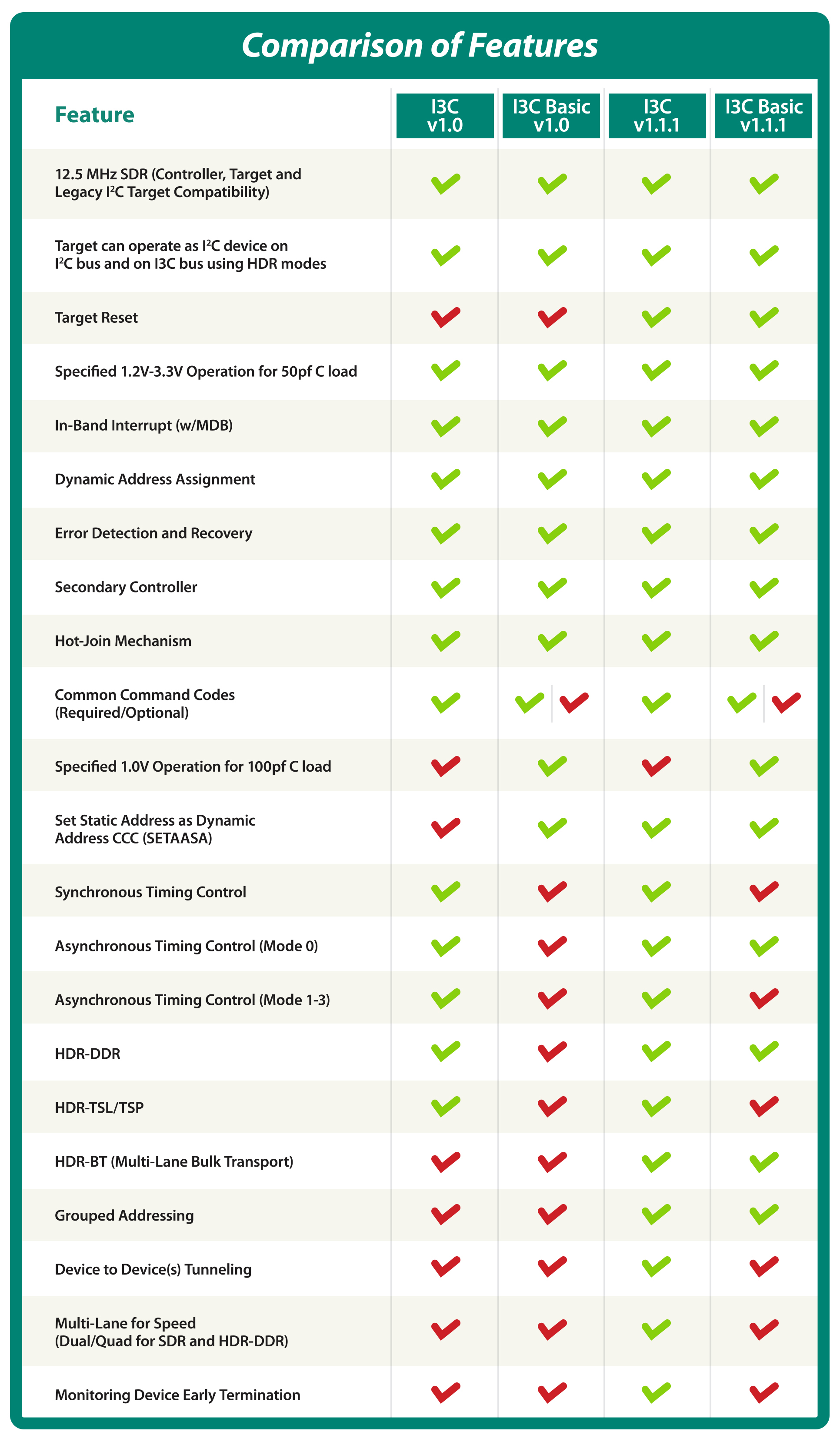
Since MIPI I3C and I3C Basic were released in 2016 and 2018, respectively, the I3C Working Group and I3C Basic Ad Hoc Working Group have evolved I3C and added more features (see the feature comparison chart at right), making it highly robust and flexible in comparison with other options. Implementation of MIPI I3C also standardizes interface design among multiple vendors to reduce design complexity. Most board-level communications that are currently using a mix of I2C and SPI can easily adopt I3C for differentiated advantages in speed, power and cost.
I3C for Speed
MIPI I3C provides high-speed communication and high bandwidth with minimal hardware requirements and 10x or greater performance improvement over I2C communications. SPI-based communications work up to 10 Megahertz (MHz) on multi-drop buses and can reach larger magnitudes in a dedicated bus operating in a point-to-point configuration. I3C provides a means of using a 12.5 MHz base clock that gives an 11 Megabits per second (Mbps) Standard Data Rate, reaching speeds up to 25 Mbps in I3C Basic and 33 Mbps in I3C in High Data Rate modes of communications.
The two-wire I3C interface also has the option of a multi-lane configuration for data. Multi-lane provides a means of further increasing the data rate to allow more throughput whenever necessary. The multi-lane option is intended to offer a similar configuration to dual and quad SPI, but also provides the added features of I3C. The use of the base clock of 12.5 MHz provides a means in which the target devices do not need to raise the base clock speed to reach higher data throughputs, offering benefits in terms of power and electromagnetic interference (EMI).
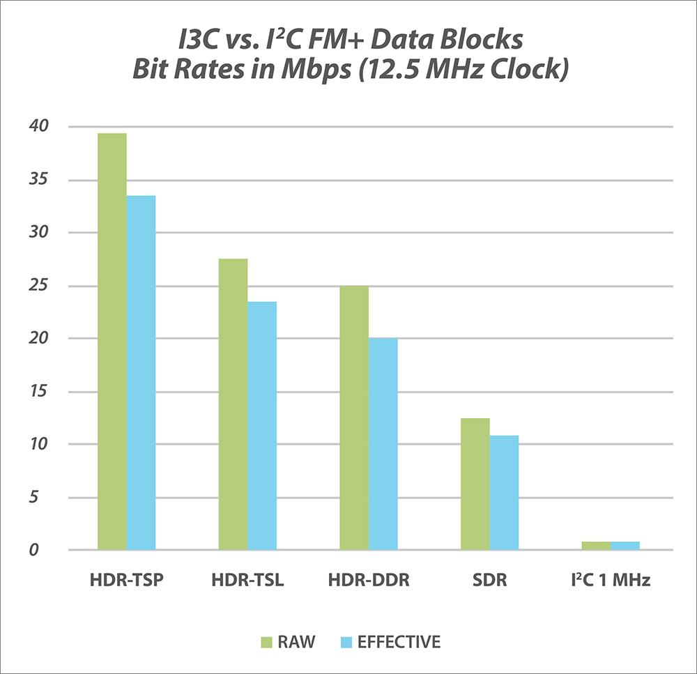
Caption: Raw and effective single-lane bit rates of the I3C modes compared with I2C FM+ (1 MHz).
Another I3C feature, In-Band Interrupts (IBI), provides speed and efficiency for communicating target events to the controller. These requests can be accompanied by payloads, which can be used to identify the type of interrupt and associated data generated by the targets.
I3C for Power
MIPI I3C provides built-in commands and features to assist system designers with their power budgets, extending the standardized voltage support of 1.2V for serial interfaces:
- Signaling plays a significant role in reducing energy per bit. More communication means more power consumption. Open-drain communications consume power when the signal communicated on the bus is low due to the current flowing through the pull-up resistor; however, push-pull communications consume power only when they are switching transitions of the (IO) drivers. I3C uses open-drain mode communication only in a few instances, such as address arbitration or acknowledgment bit. The data transfer uses the push-pull mode. By strategically leveraging both types, I3C achieves lower power consumption and faster data communication, while preserving flexibility (arbitration) and reliability (data acknowledge).
- The Enter Activity State commands that are part of the I3C protocol, combined with its support of the Hot-Join and Offline modes, enable the bus or part of the system to enter into a power-down state whenever not needed for communication.
- The Enable/Disable Target-Driven Event interrupt is another means of power preservation by suspending target-driven events and minimizing communications on the bus.
- Faster data transmission and throughput allow data to be sent in burst mode, keeping communications to a short active window. The bus and connected devices are kept free and in low power state when not used for communication.
- Broadcast Common Command Codes (CCCs) and group addressing are features of I3C that aim to reduce multiple communications to each device independently by issuing a single broadcast or multicast message to all devices. Reduced communication means lower power consumption and more downtime for buses.
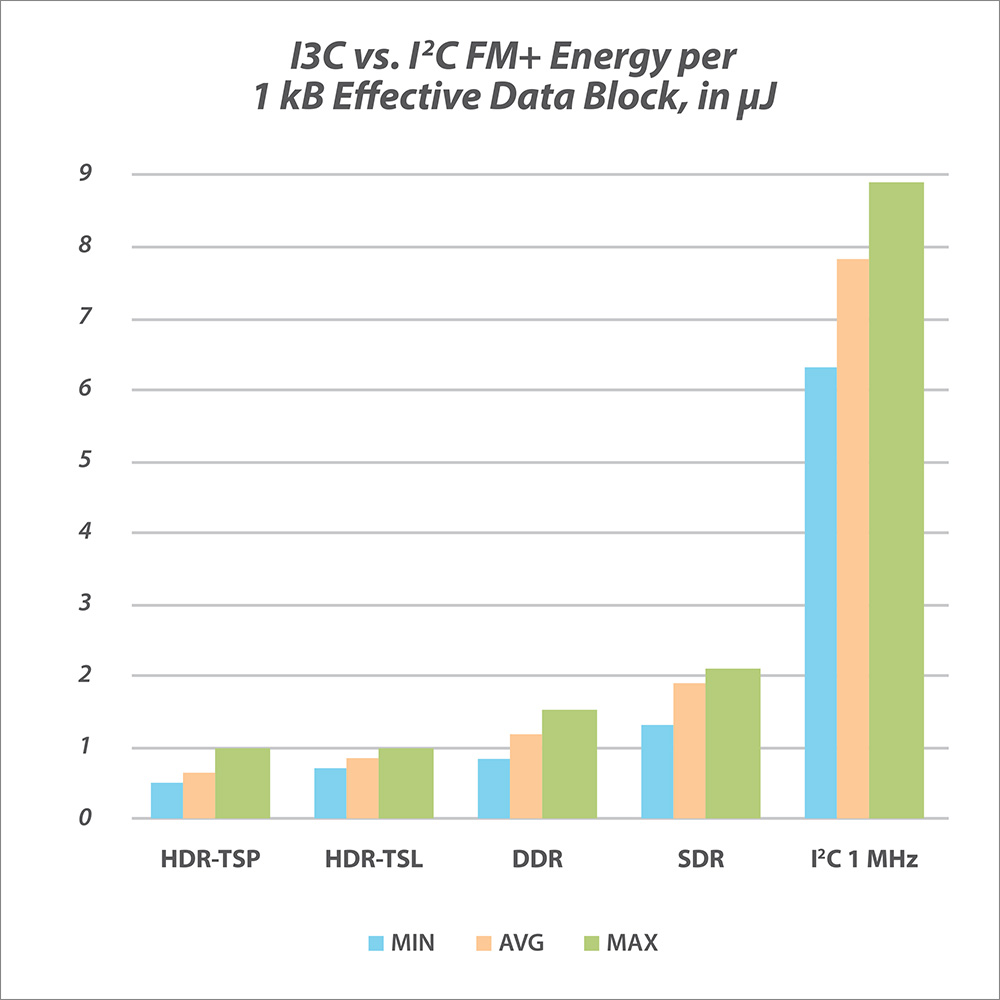
Caption: Energy (μJ) consumed for an effective single lane of 1 kB block of data for the I3C modes compared with I2C FM+ (1 MHz)
I3C for Cost
The cost of using serial buses can be explored from different angles. This evaluation will focus on bus size and optimization of tasks for better scheduling.
Interrupts are usually handled by an interrupt line, and typically a dedicated interrupt line is required for each device connected on the bus. This requirement increases the Printed Circuit Board (PCB) area for routing interrupts, as well as the number of additional General-Purpose Input/Output (GPIO) pins for each interrupt. I3C, being a true two-wire interface, allows the interrupt and reset lines to be implemented on the two wires. By doing this, the additional GPIO cost and PCB trace can be reduced. This helps in minimizing the number of buses and miniaturizing the system for compact designs.
Time constraints also contribute to cost, based on the number of devices that can be supported on a single bus. But this factor is typically thought of last in system planning, and that’s the wrong approach.
The time needed to communicate with each device increases along with the number of devices, which will affect the time constraint. These communications will reach a point where adding another device in the bus is no longer an option due to the overhead related to interrupt source identification. If the management of devices cannot be executed within the time budget, then the system designer will be forced to reduce the devices on the bus and add another bus to handle the removed devices. This will increase the area and cost of management for the devices on the system.
This can be resolved by reducing the average time required for each device. In I3C, interrupts are implemented as IBIs, which use the SDA (serial data) line to generate events from target devices and identify themselves by sending their dynamic address. Combined with the arbitration of devices, this allows multiple devices to share the bus and send an interrupt request without the need for a dedicated line. In this way, I3C brings down the costs related to PCB traces and bus management by using the two lines for different features.
Following their identification, targets send a Mandatory Data Byte (MDB), which helps the controller handle the interrupt in a proper way. The MDB is used to handle the interrupt in two ways:
- Sending an MDB defined by the target chosen from sets of reserved values: These types of interrupts can send additional data to provide more specific interrupt information. This will provide fast information, removing the need to read the interrupt-related information with a separate operation.
- Using a specific MDB value indicating a Pending Read Notification (PRN): The PRN just informs the controller that the target has data to send. It is up to the controller to decide when it is most appropriate to read the data associated with the interrupt.
An Ideal Solution for Board-Level Communications
In MIPI I3C, most of these communications are embedded and optimized within the protocol. As shown above, a few communications are needed by the IBI to identify different events from devices on the bus. In these scenarios, the bus can be used to address more devices on the same bus by taking advantage of short communication data retrievals from devices. These optimizations are aimed at saving the time needed by the interrupts and allowing more devices to be present on the bus.
Another advantage of I3C is assisting with the prioritization of tasks. I3C has a built-in system to allow prioritization of interrupts from devices by using their dynamic addresses. This prioritization is based on the IBI Arbitration, which helps in reducing the processing time required to assort events.
The duration and energy spent on interrogating each device to poll interrupts makes the bus not usable when the number of devices on the bus increases. The extra wires required by other protocols also make bus design complex and costly.
This unique combination of benefits—speed, power and cost—offered by MIPI I3C makes it an ideal solution as a low-cost, optimized protocol for board-level communication among different subsystems of an electronic system. To learn more, visit the MIPI I3C/I3C Basic specification page.
Editor's note: Eyuel will be speaking 2 November 2023 as part of the MIPI I3C – the Next-Generation Serial Communication Bus webinar, presented in partnership with Elektor.
Eyuel Zewdu Teferi has been with STMicroelectronics since 2016 and is currently a senior hardware design engineer in ST's MEMS sensor division. He has worked on projects designing and implementing interface designs for MEMS sensors. Eyuel earned his master's degree in electronics engineering in Politecnico di Torino, focusing on embedded systems. He is involved in both MIPI and JEDEC, is an active member of the MIPI I3C Working Group and is currently the vice chair of the MIPI I3C Basic Ad Hoc Working Group.