


Update: MIPI A-PHY was adopted as an IEEE standard in June 2021 and is also available as IEEE 2977-2021.
To provide additional support to developers working with the MIPI A-PHY℠ v1.0 specification, the A-PHY Working Group has released an Application Note for MIPI A-PHY Specification v1.0: Profile 1 and Profile 2 (for MIPI members), providing key performance indicators to help implementers design solutions that conform to the automotive long-reach serializer-deserializer (SerDes) physical layer specification.
MIPI A-PHY targets advanced driver assistance systems (ADAS), autonomous driving systems (ADS), in-vehicle infotainment (IVI) and other surround-sensor applications. To fit the technical attributes and cost structures of different automotive market segments, MIPI A-PHY defines two performance and immunity profiles. For each profile, the new App Note describes system validation simulation environments, noise sources considered and example simulation results, providing worst-case condition timing and electrical margins. In addition, a brief frequently asked questions (FAQs) section on just-in-time cancellers (JITCs) and stressed sensitivity / receiver interference intolerance is also included.
A-PHY profiles and speeds
MIPI A-PHY v1.0 provides an asymmetric data link in a point-to-point or daisy-chain topology, providing high-speed unidirectional data, embedded bidirectional control data and optional power delivery over a single cable.
An understanding of the two profiles and their characteristics is helpful when evaluating implementation options:
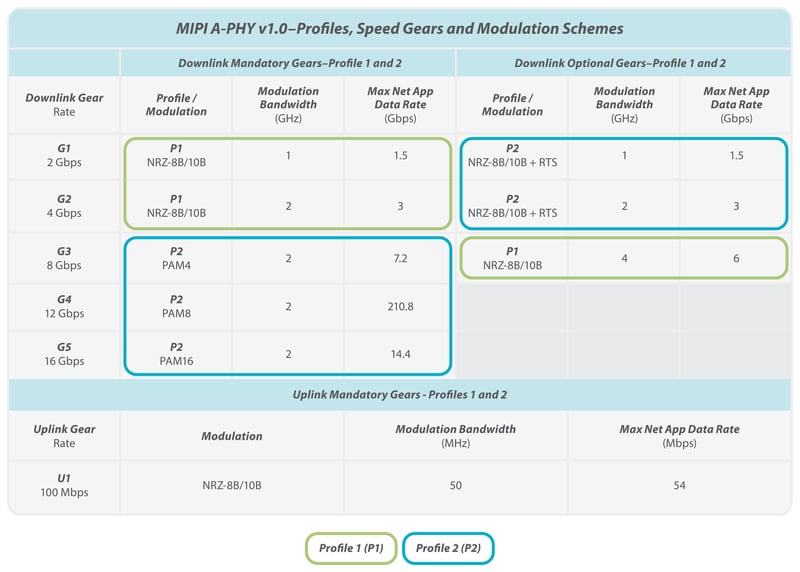
- Profile 1 (P1) is aimed at lower downlink speeds and less complex implementations, with channel attributes and design characteristics that enable lower-cost solutions. This profile is based on non-return-to-zero (NRZ) 8B/10B coding technology, and support of this profile is mandatory for downlink speed Gears 1 and 2, and optional for Gear 3.
- Profile 2 (P2) is aimed at solutions requiring higher noise immunity and downlink speeds, and is based on a dynamic pulse-amplitude modulation (PAM) coding scheme, using local physical layer retransmission and noise cancellers. Support of this profile is mandatory for downlink speed Gears 3, 4 and 5, and optional for Gears 1 and 2.
The two profiles and their associated speed gears are shown in the table below:
Validating transceiver solutions
The application note describes how A-PHY v1.0 Profile 1 and Profile 2 transceiver solutions should be validated to help ensure compliance to the A-PHY specification. Detailed "end-to-end" validation models are defined for both profiles and include the following key components:
- A-PHY source, incorporating a downlink transmitter function and an uplink receiver function
- Channel, the interconnect between source and sink
- A-PHY sink, incorporating downlink receiver function and an uplink transmitter function
- Noise sources
Due to the use of different modulation schemes, specific considerations must be taken into account when validating either Profile 1 or Profile 2 transceivers, particularly in regard to the value of the noise components used for each model. The following noise components (derived from the A-PHY specification) are described in detail within the document:
- Narrow band interference
- Channel loss
- Inter symbol interference
- RF ingress
- Bulk current injection
- Transient on-line
- Power over cable ripple noise
- Crosstalk (downlink only)
- Car noise
- Noise in analog front-end (AFE) circuitry
- Residual echo
- Jitter
Simulations were performed using the defined validation models, and stated noise parameters are provided for both profiles that cover all five speed gears, and both downlink and uplink channels. Advanced Design System (ADS) models and Matlab code examples were also created as part of this solution exercise and are included in the document for reference.
The simulation results were used to define the timing and electrical margins expected for A-PHY transceiver solutions under worst-case conditions. The application note recommends that A-PHY transceiver solutions meet or exceed these simulated performance results to help ensure their compliance to the A-PHY v1.0 specification, noting that compliance against the parameters stated in the App Note does not represent full validation of the solution.
In summary
An invaluable resource for developers implementing MIPI A-PHY v1.0 solutions, the App Note defines validation models for each profile, outlines the necessary noise components, and provides detailed simulation results that define the baseline timing and electrical margins that actual A-PHY transceiver solutions must meet under worst-case conditions.
MIPI Alliance members can download the A-PHY Application Note, ADS workspace, and MIPI A-PHY specification v1.0 on the MIPI member website (Causeway).