


I3C and I3C Basic
Frequently Asked Questions
Resources

-
Jump To
- Introduction to MIPI I3C
- Migration from Legacy I2C or Other Buses
- I3C Versions and Releases
- Up and Coming
- Naming and Terminology
- Implementation: Ecosystem
- Implementation: As a System Designer
- Implementation: As a Software Developer
- Interoperability Workshops
- Conformance Testing
- Legal & Intellectual Property Related Questions
- New Capabilities in I3C
- Limits and Performance
- Minimum Required Features
- Backwards Compatibility with I2C
- Address Assignment
- In-Band Interrupt and Hot-Join
- Common Command Codes (CCCs)
- High Data Rate (HDR) Modes
- I3C Advanced Capabilities
- Electricals and Signaling
- Bus Conditions and States
- Resets and Error Handling
- Timing Parameters
- I3C Additional Information
Introduction to MIPI I3C
-
What is MIPI I3C and I3C Basic?
MIPI I3C is a serial communication interface specification that improves upon the features, performance, and power use of I2C, while maintaining backward compatibility for most devices.
MIPI I3C Basic is technically identical to MIPI I3C, except with a reduced feature set and RAND-Z licensing
(see Section 2.11 "Legal and Intellectual Property Related Questions"). -
What does the I3C acronym mean?
The official name is MIPI Alliance Improved Inter Integrated Circuit.
-
Why is MIPI I3C being introduced?
The main purpose of MIPI I3C is threefold:
- To standardize sensor communication,
- To reduce the number of physical pins used in sensor system integration, and
- To support low power, high speed, and other critical features that are currently covered by I²C and SPI.
MIPI I3C’s purpose is now widening to cover many types of devices currently using I²C/SMbus, SPI, and UART.
-
What are the main features of MIPI I3C?
MIPI I3C carries the advantages of I2C in simplicity, low pin count, easy board design, and multi-drop (vs. point-to-point), but provides the higher data rates, simpler pads, and lower power of SPI. I3C then adds higher throughput for a given frequency, In-Band Interrupts (from Target to Controller), Dynamic Addressing, advanced power management, and Hot-Join.
-
For which applications or use cases is I3C intended to be used?
I3C was initially intended for mobile applications as a single interface that can be used for all digitally interfaced sensors. However, it is now intended for all mid-speed embedded and deeply-embedded applications across sensors, actuators, power regulators, MCUs, FPGAs, etc. The interface is also useful for other applications, as it offers high-speed data transfer at very low power levels while allowing multi-drop, which is highly desirable for any embedded system.
-
How can the MIPI I3C specifications be obtained?
MIPI I3C Specification: MIPI Alliance members have access and rights to the MIPI I3C Specification through their MIPI membership and member website. The latest adopted version is MIPI I3C v1.2.
MIPI I3C Basic Specification: MIPI Alliance made the MIPI I3C Basic v1.0 Specification [MIPI09] publicly available for download in December 2018. The latest adopted version is MIPI I3C Basic v1.2. MIPI Alliance members have access and rights to the I3C Basic specification through their MIPI membership and member website.
Non-members may download a copyright-only version of the I3C Basic specification by visiting the MIPI I3C Basic page on the MIPI Alliance website.
Migration from Legacy I2C or Other Buses
-
Why replace I²C with I3C?
While I2C has seen wide adoption over the years, it lacks some critical features – especially as mobile and mobile-influenced systems continue to integrate more and more sensors and other components. I2C limitations worth mentioning include: 7-bit fixed address (no virtual addressing), no in-band interrupt (requires additional wires/pins), limited data rate, and the ability of Targets to stretch the clock (thus potentially hanging up the system, etc.). I3C aims both to fix these limitations, and to add other enhancements.
-
Does I3C use less power than I²C?
The power consumption per bit-transfer in all I3C modes is more efficient than I²C, due to the use of Push Pull to actively drive both SCL and SDA (vs. Open-Drain) and strong Pull-Up signaling.
Further, I3C can save considerable device power through higher data rates (because the device can be put back to sleep sooner), built-in configuration and control (without intruding on the main communication protocols), In-Band Interrupt (IBI) as a low-cost wake mechanism, and the ability for Targets to shut down all internal clocks while still operating correctly on the I3C Bus.
-
How is I3C different from I²C?
I3C offers dynamic address assignment, Target-initiated communication, and significantly higher communication speeds than I²C.
-
Why replace SPI (Serial Peripheral Interface) with I3C?
SPI requires four wires and has many different implementations because there is no clearly defined standard. In addition, SPI requires one additional chip select (or enable) wire for each additional device on the bus, which quickly becomes cost-prohibitive in terms of number of pins and wires, and power. I3C aims to fix that, as it uses only two wires and is well defined.
I3C covers most of the speed range of SPI, but is not intended for the highest speed grades that really only work well with a point-to-point interface, such as for SPI Flash.
I3C Versions and Releases
-
What is new in I3C v1.2?
MIPI I3C v1.2 is primarily an editorial update to MIPI I3C v1.1.1, which includes all issues identified and corrected in Errata 02 for I3C v1.1.1 as well as other fixes for issues found by implementers. I3C v1.2 reformats the technical content of the I3C Specification to more clearly separate required features vs. optional features in different document sections. I3C v1.2 also resolves issues, and clarifies and improves upon the I3C v1.1.1 specification. However, I3C v1.2 does not include any new features or capabilities.
I3C v1.2 includes:
- New document structure which places optional features in separate sections for clarity
- Fixes for inconsistencies and other issues that were technical errors in MIPI I3C v1.1.1 (including all issues resolved by Errata 02)
- Clarifications to the requirements for Targets that support In-Band Interrupts (IBIs)
- Minor changes to the HDR-BT Mode framing, in order to provide more consistent flows for CCCs and for regular transfers, and also resolve uncertainty about when the HDR-BT CRC Blocks are sent vs. not sent
- Updated End of CCC Procedures in HDR-BT Mode that improve efficiency for Broadcast CCCs
- Clarifications on when the Controller is permitted to stall the clock during SDR and HDR transfers
- Clarifications on the timing requirements to be observed when sending either the Target Reset Pattern, HDR Exit Pattern, or HDR Restart Pattern
- Clarifications on when to use the ENDXFER CCC to configure flow control for either HDR-DDR Mode or HDR-Ternary Modes
- Clarifications on the Minimal Bus use case, as well as the requirements for special receive-only Targets that are optional for this use case
- Allowance for higher Clock-to-Data turnaround delay (tSCO) up to 20 ns, for Target implementations that cannot achieve 12 ns or that will only be used at lower I3C Bus clock speeds
-
Is I3C v1.2 compatible/interoperable with I3C v1.1.1 and earlier?
In most cases, yes. I3C v1.2 is primarily an editorial update that reorganizes the specification sections for easier readability, and also resolves some inconsistencies or areas that needed clarification compared to I3C v1.1.1 and earlier. No new features or capabilities are added. I3C v1.2 addresses all I3C v1.1.1 issues that were addressed in Errata 02.
However, some changes were made to HDR-BT Mode framing that could affect interoperability with older Controllers or older Targets; see Q19.17 for more details. Additionally, the definition of the GETMXDS CCC has changed, in order to improve flexibility for reporting a Target’s Clock-to-Data turnaround time; see Q18.28 for more details.
-
What is new in I3C Basic v1.2?
MIPI I3C Basic v1.2 is primarily an editorial update to MIPI I3C Basic v1.1.1, which includes all issues identified and corrected in Errata 01 for I3C Basic v1.1.1, as well as all applicable fixes, improvements, and clarifications that were either (A) identified and corrected in Errata 02 for I3C v1.2, and/or (B) addressed in I3C v1.2.
I3C Basic v1.2 also has the same document structure changes that were applied to I3C v1.2. Following the trend from previous I3C and I3C Basic releases, I3C Basic v1.2 is considered to be a subset of I3C v1.2. Devices that comply with I3C Basic v1.2 should be mutually interoperable with I3C v1.2, and vice versa.
Up and Coming
-
What future MIPI specifications will be leveraging I3C?
Many other MIPI Alliance Working Groups are in the process of leveraging the I3C specification. As of the writing of this FAQ, the list includes:
- Camera WG: Camera Control Interface (CCI) chapter of the MIPI Specification for Camera Serial Interface 2 (CSI-2), v4.0 [MIPI06] or later
- Debug WG: MIPI Specification for Debug Over I3C, v1.10 [MIPI15] or later
-
Are any revisions expected to MIPI I3C v1.1.1, or to earlier versions of I3C?
No. MIPI I3C v1.2 includes all known fixes in, and Errata for, I3C v1.1.1.
MIPI Alliance strongly recommends that all implementers move to MIPI I3C v1.2 which is the newest recommended version.
-
Are any revisions expected to I3C Basic v1.1.1, or to earlier versions of I3C Basic?
No. MIPI I3C Basic v1.2 includes all known fixes in, and Errata for, I3C Basic v1.1.1.
MIPI Alliance strongly recommends that all implementers move to MIPI I3C Basic v1.2 which is the newest recommended version.
-
Are there any impending fixes or errata for I3C v1.1.1 or I3C Basic v1.1.1 that should be applied now?
Note: With the release of I3C v1.2 this question has been deprecated; it is retained here for reference. See Q3.1 for what’s new in I3C v1.2.
Yes, several fixes to the I3C v1.1.1 and I3C Basic v1.1.1 specifications have been identified. MIPI has published these fixes as Errata 02 for I3C v1.1.1 and Errata 01 for I3C Basic v1.1.1. Please refer to the Errata for full details of these fixes.
MIPI Alliance has also addressed these issues by including these clarifications in the v1.2 updates to the I3C and I3C Basic specifications.
Note: MIPI Alliance strongly recommends that all implementers use the latest version of the I3C specifications with the most current published Errata.
-
Are there any revisions expected to I3C v1.2?
No, there are no pending updates at this time. However, the MIPI I3C WG meets regularly and is considering proposals to revise and extend I3C. As part of maintaining the I3C specification, the MIPI I3C WG seeks to improve the I3C specification in areas where it would benefit from clarification or additional explanation.
Please direct any comments or suggestions to MIPI Alliance.
MIPI I3C v1.2 includes all known fixes in MIPI I3C v1.1.1 and includes the issues found in all Errata. MIPI Alliance strongly recommends that all implementers move to MIPI I3C v1.2 as the newest recommended version of the I3C specification.
-
Are there any impending fixes or errata for I3C v1.2 and I3C Basic v1.2 that should be applied now?
Yes, several fixes to the MIPI I3C v1.2 and I3C Basic v1.2 specifications have been identified. MIPI is currently working to publish these as Errata, and also plans to address these issues by including these clarifications in the next update to the I3C and I3C Basic specifications.
Note: MIPI Alliance strongly recommends that all implementers use the latest version of the I3C specifications with the most current published Errata.
These fixes fall into several categories:
- Relaxed Requirements for Passive Hot-Joining Targets
- Section 4.3.5.3 defines requirements for Targets that use a passive Hot-Join method. This use case is intended for a Target that does not inherently know if it will be used on an I3C Bus or a Legacy I2C Bus. Such a Target will need to see an SDR Frame that starts with the I3C Broadcast Address (i.e., 7'h7E) before it can use any I3C-specific requests such as the Hot-Join Request. The original requirements for a passive Hot-Joining Target were strict, i.e., such a Target would need to see the SDR Frame that starts with the I3C Broadcast Address and ends with a STOP, then it would need to emit the Hot-Join Request to inform the Controller. However, this presented limitations for certain use cases, where the Target and the Active Controller both powered on at the same time. These requirements are now relaxed: a passive Hot-Joining Target is no longer required to emit the Hot-Join Request as soon as it determines that it is on an I3C Bus, and it can respond to the first ENTDAA CCC after it makes this determination (see Q17.6 and Q17.7).
- HDR-DDR Corrections
- Section 6.2.3.3 Table 83 correctly defines the Parity Adjustment bit at the falling edge of SCL clock C9 in the HDR-DDR Command Word. However, Figure 107 and Table 82 (in Section 6.2.3.2) incorrectly show this bit as reserved.
- HDR-DDR Flow Control and Transfer Termination
- Section 6.2.3.4 which defines the flow control procedures available in HDR-DDR Mode incorrectly states that all HDR-DDR flow control procedures defined in this section and its subsections are mandatory for Targets to support. This is incorrect because some of these HDR-DDR flow control procedures are optional for a Target to support; the Target will indicate which optional procedures are supported using specific bits of the GETCAP2 byte (which is returned by the GETCAPS Format 1 CCC). Once the Controller uses the GETCAPS CCC to determine which HDR-DDR flow control capabilities are supported by a Target, it can then use the ENDXFER CCC to enable these flow control procedures as needed. See also Q18.16. In addition, Targets must always allow the Controller to terminate an HDR-DDR read transfer, which has been defined since v1.0 of the I3C Specification and does not require configuration to enable (since it is always allowed).
- Section 6.2.3.4 also summarizes the default behavior of a Target when HDR-DDR flow control is not enabled. However, it incorrectly states that a Target is always obligated to send the CRC Word after the last Data Word when an HDR-DDR read transfer is terminated, even if HDR-DDR flow control has not yet been configured by the Controller. This is incorrect: the default state of the Target is to not send the CRC Word after read transfer termination. The Target will only send the CRC Word after read termination if it supports this capability (which is optional; see above) and if it had been previously configured to do so (i.e., by using the ENDXFER CCC) as defined in Section 6.2.3.4.4. See also Q19.4.
- In Section 6.2.3.4.5, several figure references are incorrect.
- Timing Control Async Mode 1 (not included in I3C Basic)
- Figure 177 and Figure 178 which show the operation of Async Mode 1 are both incorrect in several ways. For example, Figure 178 incorrectly shows EOT_C1 as the time where the Controller ACKs the IBI for this event. In fact, EOT_C1 should be the following aBE (Additional Bus Event) on the I3C Bus (i.e., after the triggering condition). Additionally, Figure 178 incorrectly shows how the Target determines both T_C1 and T_C2. In fact, T_C1 should measure the time between the triggering event and the next aBE on the I3C Bus; while T_C2 should measure the time between the IBI ACK and the first rising SCL edge after the T-Bit of the MDB. Normative text and tables in Section 6.6.3.2 define these correctly: only the figures are incorrect. See also Q20.15.
- SDR-ML Corrections (not included in I3C Basic)
- Q20.11. Section 6.7.3.4.3 Table 119 defines the T-Bit values to use on SDA[3:1] for the Padded Last Data Block for SDR-ML Read transfers. The table states that these T-Bit values should refer to “next Bytes”, but this is clearly incorrect, since there is no Data Block after the Padded Last Data Block and there will be no next bytes (i.e., the Padded Last Data Block is the end of the SDR-ML Read transfer). The definitions for these T-Bits on SDA[3:1] will be corrected to 1’b0 always. Figure 202 will be corrected to show the changes to T-Bits on SDA[3:1]. See also Q20.11.
- HDR-BT Handoff and Transition Control
- Figure 161, Figure 162, and Figure 163 show incorrect handoff windows for HDR-BT Header Blocks during the Transition byte, for cases where the addressed Target drives SCL for the HDR-BT Read transfer. In fact, the handoff point should be before the falling edge of the first clock cycle in the Transition byte, not after the falling edge. Normative text in Section 6.4.3.3.1 defines this correctly: only the figures are incorrect. See also Q19.19.
- Additionally, issues were discovered for certain HDR-BT Read transfers in Dual Lane mode, where the bits driven by the Target in the Transition_Control byte could cause parity errors if the Read transfer was terminated by the Controller. To address this, the SDA Lane bit packing for Dual Lane mode has been changed for this situation only (i.e., only for the Transition_Control byte within the HDR-BT Data Block). Figure 165 will be corrected to show the changes to SDA Lane bit packing. See also Q19.18.
- Relaxed Requirements for Passive Hot-Joining Targets
-
What new features, if any, are coming to MIPI I3C?
There are no new approved features, however the MIPI I3C WG is considering the following:
- Automotive-focused capabilities
- Security over I3C
- Improved reliability
- Speed increases
- New Multi-Lane uses
- Long Reach
- New HDR Modes
- Refining existing features
Naming and Terminology
-
What is an I3C “Controller” Device, and why was the I3C “Master” Device renamed?
As part of a terminology replacement effort across MIPI Alliance, starting with I3C v1.1.1 and I3C Basic v1.1.1 the terms Master and Slave have been deprecated. An I3C v1.0/v1.1 Master Device is now called a Controller. There is no change to the technical definition of such an I3C Device or its role on an I3C Bus. The term Controller is a better, more accurate description of the Device’s role on an I3C Bus.
Due to this change, the names of various CCCs and other, related terms have also changed starting with v1.1.1, including:
Deprecated Prior Term
I3C and I3C Basic before v1.1.1Replacement Term
I3C and I3C Basic v1.1.1 and laterMaster
Controller
Current Master
Active Controller
Secondary Master
Secondary Controller
Main Master
Primary Controller
New Master (relating to Handoff)
New Active Controller
Master-capable Device
Controller-capable Device
Mastership, Mastering the Bus, etc.
Controller Role, Control of the Bus, etc.
Mastership Request
Controller Role Request
GETACCMST CCC
GETACCCR CCC
Error Types M0 through M3
Error Types CE0 through CE3
See the question below, "What is an I3C “Target” Device, and why was the I3C “Slave” Device renamed?"
-
What is an I3C “Target” Device, and why was the I3C “Slave” Device renamed?
As part of a terminology replacement effort across MIPI Alliance, starting with I3C v1.1.1 and I3C Basic v1.1.1 the terms Master and Slave have been deprecated. An I3C v1.0/v1.1 Slave Device is now called a Target. There is no change to the technical definition of such an I3C Device or its role on an I3C Bus.
The term Target is a better, more accurate description of the Device’s role on an I3C Bus. In particular, the previous term did not describe I3C transfers, which are typically sent by the I3C Controller to individual I3C Devices or to all I3C Devices. The replacement term Target better describes how individual transfers are addressed (i.e., are “targeted”) to particular I3C Devices.
Due to this change, the names of various CCCs and other, related terms have also changed starting with v1.1.1, including:
Deprecated Prior Term
I3C and I3C Basic before v1.1.1Replacement Term
I3C and I3C Basic v1.1.1 and laterSlave
Target
Slave Reset Pattern
Target Reset Pattern
DEFSLVS CC
DEFTGTS CCC
Error Types S0 through S6
Error Types TE0 through TE6
See the question above, "What is an I3C “Controller” Device, and why was the I3C “Master” Device renamed?"
Implementation: Ecosystem
-
Who is defining the MIPI I3C Specifications?
The I3C specification is defined by the MIPI Alliance I3C Working Group (originally named the Sensor Working Group) which was formed in 2013. I3C Basic is defined by the MIPI Alliance I3C Basic Ad-Hoc Working Group which was formed in 2018.
-
Is anyone currently using I3C?
Yes, a number of companies have released products that feature integrated I3C Controller and I3C Target support. Other companies offer IP blocks and associated verification software for adding I3C Bus support into various integrated circuit designs. Some companies also offer protocol analyzers and verification hardware to help analyze I3C Bus traffic for testing and development.
-
What is the availability of development hardware for I3C prototyping, including FPGAs?
Several vendors have provided FPGA based design kits, including some low-cost FPGAs that might be good enough for smaller production runs.
-
What is the I3C IP core availability in the market?
Some vendors have started to offer Target and/or Controller IP cores for integration into ASIC devices and FPGAs, including a free-of-cost Target IP available for prototyping and integration.
Implementation: As a System Designer
-
What is the maximum capacitance load allowed on the I3C Bus?
The I3C specification lists the maximum per-Device capacitance on SCL and SDA, but the goal is that most or all Devices will be well below that. As with any Bus, capacitance alone is not sufficient to determine maximum frequency on the I3C Bus. It is important to consider maximum propagation length, effect of stubs, internal Clock-to-Data turnaround delay (tSCO) of the Targets, as well as capacitive load.
-
What is the maximum wire length for I3C communication?
The maximum wire length would be a function of speed, as all the reflections and Bus turnaround must complete within one cycle. Larger distances can be achieved at the lower speeds than at the higher ones. For example, at 1 meter (between Controller and Target), the maximum effective speed is around 6 MHz for read, to allow for clock propagation time to Target and SDA return time to Controller.
-
Can I²C repeaters be used for I3C?
Not directly, for a couple of reasons:
- The I3C Bus uses Push-Pull mode for data transfers, and
- Much higher speeds. Most I2C repeater devices are quite limited in speed, because of the lag effect of changing states on SCL and SDA due to both series-resistance and assumptions about Open-Drain.
-
Will the I²C devices respond to I3C commands?
No. The I3C CCCs are always preceded by the I3C Broadcast Address, 7’h7E. Since the I2C specification reserves address 7’h7E, no Legacy I2C Target will match the I3C Broadcast Address, and thus no Legacy I2C Target would respond to the I3C commands. Likewise, the Dynamic Addresses assigned to I3C Devices would not overlap the I2C static addresses, so no I2C device would respond to any I3C address – even if it could see it.
-
How are communication conflicts resolved on the I3C Bus?
Targets are only allowed to drive the Bus under certain situations. Besides during a read, and when ACKing their own address, Targets may also drive SDA after a START (but not Repeated START) during the arbitrable Address Header. After a START, the I3C Bus reverts back to Open-Drain mode and the Controller enables the Open Drain class Pull-Up; thus, the Target that drives a low value (i.e., logic 0) would win arbitration.
For conflicts that arise under other circumstances (i.e., not during the arbitrable Address Header), the Controller can use various recovery methods if a Target is driving SDA at the wrong time. For example, if a Target is reset and loses track of the clock, or if there is reflection or interference on the SCL line that causes misinterpretation of SCL pulses, then the Target and Controller could be out of sync and the T-bit could be misplaced. In this situation, the Controller will not know when it is appropriate to drive SDA to abort the Read, since the Target’s view of the clock would likely not match the Controller’s count of intended SCL clock pulses. The Controller can recover from stuck SDA situations by driving repeated SCL clock pulses and attempting to generate a Repeated Start, or optionally by holding SCL level for 150 μs to release the SDA line (if supported by the Target).
Note:
- For I3C v1.1.1 and earlier: see Section 5.1.10.2.6 for the stuck SDA handling procedure.
- For I3C v1.2 and later: see Section 4.3.8.2.6 for the stuck SDA handling procedure.
-
Can I3C Devices cause the communication Bus to hang?
Unlike I²C, there is no natural way to hang the I3C Bus. In I²C, clock stretching (where the Target holds the clock low, stopping it from operating) often causes serious problems with no fix: there’s simply no way to get the Target’s attention if it has hung the Bus. By contrast, in I3C only the Controller drives the clock (except for specific situations; see Q7.8), and so the Target performs all actions on SDA relative to that clock, thereby eliminating the normal causes of such hangs.
Further, since I3C is designed to ensure that Targets can operate their back-end I3C peripheral off the SCL clock (vs. oversampling), any problems elsewhere in the Target won’t translate into Bus hangs.
If a system implementer is highly concerned about a Target accidently locking itself, then a separate hard-reset line could be used. Alternatively, the I3C v1.1.1 and I3C Basic v1.1.1 specifications add a new feature called Target Reset for resetting non-responsive Targets: if the Controller emits the Target Reset Pattern (a defined unique Bus pattern that does not otherwise occur during regular communication), then the Devices on the Bus will treat it just like a hardwired reset line.
This question has been updated for I3C v1.1.1 and I3C Basic v1.1.1.
-
Will all I3C Devices be compatible with all CCCs?
No. Some CCCs are mandatory, whereas others are optional or conditionally supported, and a given I3C Device will either support them or not, depending upon the Device’s capabilities. See the Minimum Required Features section for the question, "Which features are required for a Device to be a compliant I3C Target?" and the Common Command Codes (CCCs) section for the question, "Which Dynamic Address Assignment CCCs is a Device required to support?".
-
When can an I3C Target drive the SCL line?
A Target is only allowed to drive the SCL line in the following situations:
- In HDR-Ternary Modes: When the Target is responding to an HDR-Ternary Read command initiated by the Controller and addressed to that Target’s Dynamic Address.
- For I3C v1.1.1 and earlier: see Section 5.2.3.3.
- For I3C v1.2 and later: see Section 6.3.3.3.
- In HDR-BT Mode: When the Target is responding to an HDR-BT Read command initiated by the Controller and addressed to that Target’s Dynamic Address, but only when the Controller indicates this in the Control byte of the HDR-BT Header Block. See also Q24.8.
- For I3C v1.1.1 and earlier: see Section 5.2.4.3.1.
- For I3C v1.2 and later: see Section 6.4.3.3.1.
- In HDR-Ternary Modes: When the Target is responding to an HDR-Ternary Read command initiated by the Controller and addressed to that Target’s Dynamic Address.
Implementation: As a Software Developer
-
Are there any companion MIPI I3C Specifications that enable software development?
Yes. The following MIPI specifications are expected to help with software development:
- MIPI Specification for I3C Host Controller Interface (I3C HCI), v1.2 [MIPI12]
Creates a standard definition that allows a single OS driver (also known as ‘in-box driver’) to support I3C hardware from several vendors, while also allowing vendor-specific extensions or improvements. The target audience of the HCI specification is application processor host controllers; in particular, developers of host controller (i.e., I3C Primary Controller) hardware, and developers of I3C host controller software.
- MIPI Specification for Discovery and Configuration (DisCo), v1.0 [MIPI03]
Describes a standardized device discovery and configuration mechanism for interfaces based on MIPI specifications, which can simplify component design and system integration. Also oriented to application processors.
- MIPI DisCo Specification for I3C, v1.0 [MIPI04]
Allows operating system software to use ACPI (Advanced Configuration and Power Interface) structures to discover and configure the I3C host controller and attached I3C Devices in ACPI-compliant systems. Also oriented to application processors.
In addition to these MIPI specifications, several supporting documents are also available:
- I3C Application Note: General Topics, App Note v1.1 [MIPI05] has been developed to help ASIC hardware developers, system designers, and others working in the more deeply embedded I3C Devices.
- I3C Application Note: Virtual Devices and Virtual Targets, App Note v1.0 [MIPI19] provides context on several advanced use cases for I3C Devices that expose multiple Targets or present Virtual Devices on the I3C Bus, as well as implementation considerations for such I3C Devices.
- I3C Application Note: Hot-Join, App Note v1.0 [MIPI21] provides specific guidance on Targets that support the Hot-Join Request in order to announce their presence on an I3C Bus, as well as the expected configuration of such Targets.
The I3C WG plans to develop additional Application Notes that will cover new features and capabilities included in I3C and I3C Basic. - MIPI Specification for I3C Host Controller Interface (I3C HCI), v1.2 [MIPI12]
-
Are there software libraries available for I3C?
Yes. Core I3C infrastructure has been added to the Linux Kernel as part of the I3C subsystem. The I3C subsystem also includes drivers for several I3C Controller devices and IP core implementations, including MIPI I3C HCI–compliant Host Controllers (see [MIPI12]).
The current list of Linux Kernel Patches for the I3C subsystem can be accessed via [LINX01].
Interoperability Workshops
-
What is a MIPI I3C Interoperability Workshop?
It is a MIPI Alliance sponsored event where different vendors bring their I3C implementations and check interoperation with other vendors.
-
What is the output from a MIPI I3C Interoperability Workshop?
There are three major outputs from a MIPI I3C Interoperability Workshop:
- Participating vendors can get detailed information about how well their I3C implementations interoperate with other vendors’ implementation. Vendors can also compare their results with one another.
- MIPI Alliance can generate an overall picture of the industry state-of-the-I3C-implementaion. For example, how many vendors have implemented I3C, and how many implementations pass or fail against one another.
- The MIPI I3C Working Group gets better understanding about any major issues with the I3C specification. The WG can then leverage that learning by adding to this FAQ, other supporting documents (such as Application Notes, per the question, "Are there any companion MIPI I3C Specifications that enable software development?" in the Implementation: As a Software Developer section), and possible future revision of MIPI I3C specifications.
-
Are MIPI I3C Interoperability Workshops an ongoing activity?
Yes, these are typically hosted at least once per year, based on interest from various I3C device implementers. Workshops have typically been co-located with regularly scheduled MIPI Member Meetings.
-
Who can attend or participate in a MIPI I3C Interoperability Workshop?
In general, any MIPI Alliance members who have I3C hardware ready to interop can participate. Additionally, I3C Interoperability Workshops have historically been open to other I3C hardware implementers who are not MIPI Alliance members, in order to test interoperability with I3C Basic.
-
What HW/SW is typically needed to participate in a MIPI I3C Interoperability Workshop?
While this could change in future, the minimal requirements to date have been the availability of a board with an I3C Device that can connect to other Devices via the three wires SDA, SCL, and GND. It’s also useful to have software (e.g., running on a laptop connected to the board and I3C Device) to interactively view transmitted and received Bus communications, but this might not be required for Targets. Currently there are solutions working at 3.3V and 1.8V.
-
Are there any I3C Interoperability Workshops planned for I3C or I3C Basic?
MIPI Alliance has been hosting I3C Interoperability Workshops in conjunction with selected in-person MIPI Member Meetings, typically once per year.
Conformance Testing
-
What is a MIPI Conformance Test Suite (CTS)?
A MIPI WG develops a Conformance Test Suite (CTS) document in order to improve the interoperability of products that implement a given MIPI interface specification. The CTS defines a set of conformance or interoperability tests whereby a product can be tested against other implementations of the same specification.
-
Is there a MIPI CTS for I3C?
Yes, MIPI Alliance has released a CTS for I3C v1.1.1 and I3C Basic v1.1.1 [MIPI16].
-
What is the scope of tests for the I3C CTS?
The CTS tests are designed to determine whether a given product conforms to a subset of the common I3C requirements defined in both I3C vand I3C Basic (i.e., the requirements that are common to both specifications, since I3C Basic is a subset of I3C). The scope of this version of the CTS is intentionally limited, in order to meet time-to-market requirements imposed by the rapid adoption of I3C in the marketplace, focusing on:
- SDR-only Devices without optional I3C capabilities,
- All Controller and Target Error Detection and Recovery methods, and
- Basic HDR Enter/tolerance/Restart/Exit procedures. However, specific HDR Modes are not covered by this version of the CTS.
Considering the CTS a living document, the I3C WG plans to continue expanding the scope of the CTS through future revisions or subordinate CTS documents for specific features or capabilities (e.g., HDR Modes). The growing set of CTS documents should eventually encompass a broad array of all required and optional features of both the I3C specification and the I3C Basic specification.
The CTS tests are organized as Controller DUT tests (Device Under Test) and Target DUT tests. Tests for each are presented in the order in which they appear in the I3C specification, to simplify identification of pertinent detail between the two documents.
-
Does the I3C Interoperability Workshop follow the I3C CTS?
Interoperability Workshops will ultimately follow the tests identified in the I3C CTS, as and when such events can be arranged by MIPI Alliance.
-
What details are provided for each I3C CTS test case?
Each test in the I3C CTS contains:
- A clear purpose
- References
- Resource requirements
- Tracked last technical modification
- Discussion
- All test case detail (i.e., Setup, Procedure, Results, and Problems).
DC/AC parametric requirements are embedded in each test (not split out into a separate PHY-related CTS or subsection).
Legal & Intellectual Property Related Questions
-
Is MIPI I3C Basic royalty free?
The parties that directly developed the MIPI I3C Basic specification have agreed to license all implementers on royalty free terms, as further described in the I3C Basic specification document [MIPI08]. Further, all implementers of the I3C Basic specification must commit to grant a reciprocal royalty free license to all other implementers if they wish to benefit from these royalty free license commitments. And, of course, MIPI itself does not charge royalties in connection with its specifications. MIPI’s intent is to create a robust royalty free environment for all implementers of I3C Basic.
No set of IPR terms can comprehensively address all potential risks, however. The terms apply only to those parties that agree to them, for example, and the scope of application is limited to what is described in the terms. Implementers must ultimately make their own risk assessment.
-
What license terms apply to MIPI I3C v1.x?
MIPI’s regular IPR terms apply to the full MIPI I3C specification. MIPI’s terms require that members make licenses available only to other members, as described in the MIPI Membership Agreement and MIPI Bylaws. To benefit from the license commitments, a party must be a MIPI member.
For features that are included in MIPI I3C Basic, a MIPI member can implement under the regular IPR terms, or can opt to implement the feature under the I3C Basic framework. If a member opts in to the I3C Basic framework, then they must grant the reciprocal licenses required under that framework. MIPI Alliance members are not required to participate in the I3C Basic license framework, however. Features of I3C 1.x that are not included in I3C Basic are subject only to MIPI’s regular IPR terms.
Prior to the release of I3C Basic, MIPI had made certain versions of the full MIPI I3C specification available for public review, under “copyright only” terms – that is, MIPI published the specification, but noted that no rights to implement the specification were granted under any party’s patent rights. MIPI no longer publishes the full I3C specification publicly. A non-member is not granted any right to implement the full MIPI I3C 1.x specification, either by MIPI or any MIPI member.
I3C Basic is available to non-members, as described in the Introduction to MIPI I3C section, in the question, "How can the MIPI I3C specifications be obtained?"
New Capabilities in I3C
-
Can I3C Targets initiate communication (i.e., interrupt the Controller)?
Yes, Targets can initiate communication using In-Band Interrupt requests. Communication conflicts are solved by Target Address Arbitration.
-
How can Controllers and Targets communicate on the I3C Bus?
The basic byte-based messaging schemes used in I²C and SPI map easily onto I3C. Additionally, a set of Common Command Codes (CCCs) has been defined for standard operations like enabling and disabling events, managing I3C-specific features (e.g., Dynamic Addressing, Timing Control), and other functions. CCCs are either Broadcasted (i.e., sent to all Devices on the I3C Bus), or else Directed to a particular Device on the I3C Bus (i.e., by Address).
CCCs do not interfere with, and do not consume any of the message space of, normal Controller-to-Target communications. That is, I3C provides a separate namespace for CCCs.
Note:
- For I3C v1.1.1 and earlier: see Table 16 in Section 5.1.9.3 for the main table of CCCs.
- For I3C v1.2 and later: see Table 16 in Section 4.3.7.3 for the main table of CCCs.
-
What are CCCs (Common Command Codes) and why are they used?
CCCs are the commands that an I3C Controller uses to communicate to some or all of the Targets on the I3C Bus. The CCCs are sent to the I3C Broadcast address (which is 7’h7E) so as not to interfere with normal messages sent to a Target. In other words, CCCs are separated from the standard “content protocol” used by normal messages, such as Private Write and Read transfers (in SDR Mode).
The CCCs are used for standard operations like enabling/disabling events, managing I3C-specific features, and other Bus operations. CCCs can be either Broadcasted (i.e., sent to all Devices on the I3C Bus), or else Directed to specific Devices on the I3C Bus (i.e., by Address). All CCC command number values are allocated by MIPI Alliance, and some values are reserved for specific purposes including MIPI Alliance enhancements and other extensions. See the Common Command Codes (CCCs) section for the question, "What are Vendor / Standard Extension CCCs, who can use them, and how are they differentiated among different uses?").
-
How are the following similar and/or different: In-Band Interrupt, Hot-Join, and Controller Role Request (IBI / HJ / CRR)?
All three are special, in-band methods that allow the Target to notify the Controller of a new request or state, without having to wait for the Controller to query or poll the Target(s). The term ‘in-band’ refers to doing this via the I3C Bus wires/pins themselves, rather than using methods requiring extra wires/pins.
- In-Band Interrupt (IBI): A Target uses an IBI Request to notify the Controller of a new state or event. If the Target so indicates in the BCR, then an IBI may include one or more following data bytes. A Target can only use IBI if it has indicated the intent to do in its BCR.
If the Target indicates it will send data with an IBI, then it is required to always send at least 1 byte, called the Mandatory Data Byte (MDB). Starting with I3C v1.1, the MDB is coded following certain rules. Any optional data bytes after the MDB iswill be a contract between Controller and Target. After sending the last data byte, the Target is required to use the T-Bit mechanism to end the IBI data payload. - Hot-Join (HJ): A Hot-Join Request is used only by a Target that hasn’t yet been assigned a Dynamic Address and is attached or awakened on the I3C Bus after the Primary Controller has initialized it. The Hot-Join Request uses a fixed address which is reserved for this purpose only. The Controller will recognize this fixed address and then initiate a new Dynamic Address Assignment procedure. However, a Target cannot use the Hot-Join Request before verifying that the I3C Bus is in SDR Mode. No data bytes are sent after the address of a Hot-Join Request.
- Controller Role Request (CRR): A Secondary Controller (including the Primary Controller, once it has given up the Controller Role) sends a CRR when it wants to become Controller of the I3C Bus. If the Active Controller accepts the CRR, then it will issue a GETACCCR CCC to pass the Controller Role to the requesting Secondary Controller. It is also possible for the Active Controller to initiate handoff on its own without any Target initiating an CRR, for example when a Secondary Controller wants to return control. No data bytes are sent after the address of a Controller Role Request.
- In-Band Interrupt (IBI): A Target uses an IBI Request to notify the Controller of a new state or event. If the Target so indicates in the BCR, then an IBI may include one or more following data bytes. A Target can only use IBI if it has indicated the intent to do in its BCR.
Limits and Performance
-
What is the maximum number of I3C Devices per Bus?
In I3C v1.1 and I3C Basic v1.0 the maximum number of I3C Target Devices was limited to 11. However, this limit was calculated based on typical electrical parameters, whereas different system designs might present other limitations or challenges. Also, the actual number of Targets presented on the Bus could be higher if some of the I3C Devices enable Bridging (see the I3C Advanced Capabilities section for the question, "Does the I3C Bus support Bridges?") or present Virtual Targets (see the I3C Advanced Capabilities section for the questions,"What is a Virtual Target?") with unique Dynamic Addresses.
Starting with I3C v1.1.1 and I3C Basic v1.1.1 the maximum number of I3C Target Devices is no longer stated as a fixed number. Instead, system designers should determine a limit that satisfies all I3C electrical requirements, based on the particular system’s unique layout and the unique selection of I3C Devices to be used on the Bus.
Note:
- For I3C v1.1.1 and earlier: See Section 6 for the electrical specifications of I3C.
- For I3C v1.2 and later: See Section 4.3.11 for the electrical specifications of I3C.
-
Can there be more than one I3C Target inside a chip?
Yes, multi-Target I3C chips are possible. I3C v1.1 also defines Virtual Target capabilities. See the I3C Advanced Capabilities section for the questions,"What is a Virtual Target?" for examples of Virtual Targets.
Note: For additional details about various types of multi-Target I3C Devices, see the I3C Application Note: Virtual Devices and Virtual Targets [MIPI19] at Section 5.
-
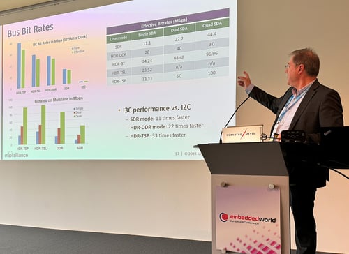
What is the bit rate for I3C?
I3C has several Modes, each with one or more associated bit rates.
The base raw bitrate for SDR Mode is 12.5 Mbps, with 11 Mbps real data rate at 12.5 MHz clock frequency. This is the only Mode supported in both I3C v1.0 and I3C Basic v1.0.
The maximum raw bitrate is 33.3 Mbps at 12.5 MHz, with real data rate of 30 Mbps. This is achieved vi HDR Modes that are currently only available in I3C v1.x (i.e., not available in I3C Basic v1.0).
Most traffic will use the 10–11 Mbps rate, while large messages can use one of the optional higher data rate (HDR) Modes or optional Multi-Lane transfers, which are available in I3C v1.1+ or I3C Basic v1.1.1.
Note: This question was updated for I3C v1.1.1. The Controller should use the GETCAPS CCC (formerly named GETHDRCAPS in I3C v1.0) to determine which optional HDR Modes are supported for a given Target.
- For I3C v1.1.1 and earlier: See Section 5.1.9.3.19 for the GETCAPS CCC definition.
- For I3C v1.2 and later: See Section 4.3.7.3.19 and Section 5.4 for the GETCAPS CCC definition.
-
Is it possible to have multiple Controllers on the same I3C Bus?
Yes, I3C allows for multiple Controllers on the same Bus. However, only one Controller can have control of the Bus (i.e., can possess the Controller Role) at any given time.
An I3C Bus has one Primary Controller that initially configures the Bus and acts as the initial Active
Controller. Optionally, the Bus can also have one or more Secondary Controller Devices; these initially act as Targets, but any one of them can send the Active Controller a Controller Role Request (CRR) to ask to take over the role of Active Controller. Once the Active Controller agrees to a CRR and transfers Bus control (i.e., transfers the Controller Role) to a requesting Secondary Controller Device, the requesting Device then becomes the new Active Controller.
Note: The previous Active Controller (including the Primary Controller) can attempt to regain Bus control by performing this same CRR process. Once the previous Active Controller passes the Controller Role to another Controller-capable Device, it typically acts as a Target (i.e., with limited scope) until it receives the Controller Role again. The terms Active Controller and Secondary Controller reflect the current role of the Device at any given time, not the Device’s initial configuration or capabilities.
If the Active Controller crashes or becomes unresponsive, then other Controller-capable Devices may use the optional Error Type DBR procedure to test the Bus and regain control if necessary.
Note: This question was updated for I3C v1.1.1 and I3C Basic v1.1.1.
For I3C v1.1.1 and earlier:- See Section 5.1.10.1.8 for the Error Type DBR procedure; and
- See Section 5.1.7 for more details on I3C Buses with multiple Controllers.
For I3C v1.2 and later:
- See Section 4.3.8.1.8 for the Error Type DBR procedure; and
- See Section 6.5 for more details on I3C Buses with multiple Controllers.
-
Can a Target indicate any speed limit that it might have?
All Targets that comply with I3C v1.1.1 and earlier must be tolerant of the 12.5 MHz maximum frequency, and all Targets must be able to manage those speeds for CCCs. However, Targets may limit the maximum effective data rate for private messages – either write, read, or both.
Note: See Q18.28 for updated guidance on Targets that comply with I3C v1.2 and later.
-
Is there a maximum limit to I3C Bus payload length?
By default, there is no limit to the maximum message length. However, to reduce Bus availability latency across multiple Targets, the I3C Bus allows Controller and Target to negotiate for maximum message lengths. This is done with the SETMRL (Set Maximum Read Length) and SETMWL (Set Maximum Write Length) CCCs. Further, the Controller can terminate a Read, which makes it possible to regain control of the Bus while in a long message (see Q23.24).
Minimum Required Features
-
Which features are required for a Device to be a compliant I3C Controller?
A compliant I3C Device that can fulfill the Controller Role is required to:
- Assign a unique Dynamic Address to any I3C Targets on the I3C Bus, using any combination of the ENTDAA, SETDASA, and SETAASA CCCs that is appropriate for such I3C Targets.
- The specific CCCs and known Static Addresses (if any) must be a prior configuration, i.e., already known to the system designer.
- Note that the SETAASA CCC was not defined in MIPI I3C v1.0, it was added in v1.1.
- Manage its Pull-Up structures, including the Open Drain class Pull-Up and High-Keeper Pull-Up for both SDA and SCL. See also Q21.3 and Q21.4 for more information on these Pull-Up structures.
- Manage START requests and Address Header arbitration in Open Drain mode.
- Recover Target Devices using the Error Recovery Escalation Model.
- Support all of the CCC commands that are mandatory for Controllers, including ENEC, DISEC, ENTDAA, SETDASA, RSTDAA, GETCAPS, RSTACT, GETPID, GETBCR, GETDCR, and GETSTATUS.
Note: The requirements above apply to the I3C Device that is the Primary Controller of its I3C Bus (i.e., the first Active Controller). An I3C Device that is a Secondary Controller during Bus initialization (or one that subsequently joins after Bus initialization) does not need to meet all of these requirements.
For I3C v1.1.1 and earlier:
- See Section 5.1.3.1 for the full requirements of the Pull-Up structures;
- See Section 5.1.4.2 for the definition of the Dynamic Address Assignment procedure;
- See Section 5.1.10 for the Error Detection and Recovery methods; and See Section 5.1.7 for specific requirements for I3C Buses with multiple Controller-capable Devices, including reduced-function Secondary Controllers.
For I3C v1.2 and later:
- See Section 4.3.3.1 for the full requirements of the Pull-Up structures;
- See Section 4.3.4.2 for the definition of the Dynamic Address Assignment Procedure;
- See Section 4.3.8 for the Error Detection and Recovery methods; and
- See Section 6.5 for specific requirements for I3C Buses with multiple Controller-capable Devices, including reduced-function Secondary Controllers.
- Assign a unique Dynamic Address to any I3C Targets on the I3C Bus, using any combination of the ENTDAA, SETDASA, and SETAASA CCCs that is appropriate for such I3C Targets.
-
Which features are required for a Device to be a compliant I3C Target?
A compliant I3C Device that can fulfill the role of Target is required to:
- Accept any valid Dynamic Address assigned by the Active Controller, using any or all of the supported methods (i.e., ENTDAA, SETDASA, and/or SETAASA; see Q18.7). Note that some of these methods require an I2C Static Address.
- If the ENTDAA method is supported, then the Device must have a MIPI Provisional ID and a MIPI-compliant DCR.
- If the Device will use Hot-Join to request a Dynamic Address (see Q17.3), then the ENTDAA method must be supported.
- Detect when it is addressed by its assigned Dynamic Address in SDR Mode, and respond to any I3C Private Read or Private Write transfers (as appropriate for the I3C content protocol).
- If the Target supports Group Addressing, then it must also respond to I3C Private Write transfers in SDR Mode that are sent to any of its assigned Group Addresses (as above).
- Use the T-Bit to signal the end of an ongoing I3C Private Read transfer or IBI data payload (when addressed) at the end of the valid read data to be sent, where the length of such transfers is limited by the configured Maximum Read Length (see Q18.18).
- Terminate an ongoing I3C Private Read transfer or IBI data payload if the Controller pulls SDA to 1'b0 during the T-Bit before the end of the valid read data to be sent (see Q17.14 and Q23.24).
- Respond to the mandatory CCCs for Targets, including ENEC, DISEC, RSTDAA, GETCAPS, GETSTATUS, and RSTACT
- Note that other CCCs might also be conditionally required, such as GETBCR, GETDCR, and GETPID.
- Detect when the Active Controller enters any HDR Mode, using the ENTHDR0 – ENTHDR7 CCCs, and either:
- If the Target supports that HDR Mode: Monitor Bus activity according to the HDR Mode’s signaling and coding, and respond appropriately to any HDR Read or HDR Write transfers that are addressed to the Device’s Dynamic Address (or HDR Write transfers that are addressed to an assigned Group Address, if applicable).
Or - If the Target does not support that HDR Mode: Ignore all activity on the Bus until the Target sees the HDR Exit Pattern.
- If the Target supports that HDR Mode: Monitor Bus activity according to the HDR Mode’s signaling and coding, and respond appropriately to any HDR Read or HDR Write transfers that are addressed to the Device’s Dynamic Address (or HDR Write transfers that are addressed to an assigned Group Address, if applicable).
- Implement Error detection and recovery methods for a Target, including Error Types TE0 through TE5.
- Detect the Target Reset Pattern either on its own, or when preceded by one or more RSTACT CCCs in the same SDR frame (see Q23.12 and Q27.13); then take the configured reset action,
Note:
For I3C v1.1.1 and earlier:
- See Section 5.1.4.2 for the definition of the Dynamic Address Assignment procedure;
- See Section 5.1.10 for the Error Detection and Recovery methods;
See Section 5.1.11 for Target Reset; and - See Section 5.2 and Section 5.2.1 for specific requirements on entering HDR Modes and using the HDR Exit Pattern.
For I3C v1.2 and later:
- See Section 4.3.4.2 for the definition of the Dynamic Address Assignment procedure;
- See Section 4.3.8 for the Error Detection and Recovery methods;
See Section 4.3.9 for Target Reset; and - See Section 4.3.10 for specific requirements on entering HDR Modes and using the HDR Exit Pattern.
- Accept any valid Dynamic Address assigned by the Active Controller, using any or all of the supported methods (i.e., ENTDAA, SETDASA, and/or SETAASA; see Q18.7). Note that some of these methods require an I2C Static Address.
-
What are the requirements for an I3C Bus initialization procedure?
The steps needed for I3C Bus initialization will vary based on the system requirements, the I3C Device capabilities, and the intended use case. However, several common steps are usually part of I3C Bus initialization:
- Send the first I3C Address Header (i.e., a START followed by 7'h7E and a RnW bit of 0) with FM/FM+ timing, so that any I3C Targets acting as Legacy I2C Targets will know that they are on an I3C Bus and can disable their Spike Filters (see Q15.4).
- This step should be done before other steps, otherwise such Targets will not know with certainty that they are on an I3C Bus.
- For I3C v1.1.1 and earlier: see Section 5.1.2.1.1
- For I3C v1.2 and later: see Section 4.3.2.1.1
- Send the SETBUSCON Broadcast CCC to set the Bus context and inform all Targets of the higher-level protocol that will be used on this Bus.
- For I3C v1.1.1 and earlier: see Section 5.1.9.3.31
- For I3C v1.2 and later: see Section 4.3.7.3.27
- Acknowledge (i.e., provide ACK to) any Hot-Join Requests that I3C Targets might send.
- If any Targets have Static Addresses, then use the SETDASA and/or SETAASA CCCs to assign Dynamic Addresses to these Targets.
- For all other Targets that support the Dynamic Address Assignment procedure, use the ENTDAA CCC to assign Dynamic Addresses to these Targets.
- If any Secondary Controllers are detected, then use the DEFTGTS CCC to send a report of all known Target devices.
- Detect all Target capabilities using the GETCAPS CCC, and configure all Targets appropriately for the use case.
Note: In some places in the I3C Specification, step #1 above (i.e., sending the first I3C Address Header with FM/FM+ timings) is recommended to be sent “after Bus initialization”. However, this is not correct: the first I3C Address Header with FM/FM+ timing should typically be sent before other Bus initialization steps, i.e., to disable the Spike Filter before sending any CCCs that such Targets would be expected to receive.
- Send the first I3C Address Header (i.e., a START followed by 7'h7E and a RnW bit of 0) with FM/FM+ timing, so that any I3C Targets acting as Legacy I2C Targets will know that they are on an I3C Bus and can disable their Spike Filters (see Q15.4).
Backwards Compatibility with I2C
-
Is I3C backward compatible with I²C?
Yes, most Legacy I²C Target devices can be operated on an I3C Bus, provided they have a 50 ns spike (glitch) filter and do not attempt to stall the clock. Such use will not degrade the speed of communications to I3C Targets; it will require decreased speed only when communicating with the I²C Targets.
I3C supports Legacy I2C Target devices using Fast-mode (Fm, 400 KHz) and FastMode+ (Fm+, 1 MHz) with the 50 ns spike filter, but not the other I2C modes, and not I2C devices lacking the spike filter, or I2C devices that stretch the clock.
-
Can I3C Devices operate on a Legacy I²C Bus?
I3C Target Devices that have a Static Address can operate as I2C Targets on an I2C bus; optionally, they can also have a 50 ns spike filter. However, once such a Device sees the I3C Broadcast Address (7'h7E) it is required to disable its spike filter, and it must also process all applicable Broadcast CCCs before it is assigned a Dynamic Address (see also Q16.6). Additionally, once such a Target is assigned a Dynamic Address, it will only respond to the assigned Dynamic Address.
Additional requirements also apply; see also Q15.4.
- For I3C v1.1.1 and earlier: See Section 5.1.1.1 and Section 5.1.2.1 for Static Address requirements.
- For I3C v1.2 and later: See Section 4.3.1.1 and Section 4.3.2.1 for Static Address requirements.
-
Can I3C and I²C co-exist on the same bus?
Yes, both I3C and I²C can share the same bus, with some limitations:
- I3C does not support Legacy I2C Controller Devices, because they cannot share the Bus with I3C Devices.
- I3C does support many Legacy I2C Target Devices, on the condition that they meet certain guidelines; see also Q15.1 regarding backward compatibility.
Note: This question has been updated for I3C v1.1.1 and I3C Basic v1.1.1.
-
How does an I3C Target behave with an I2C Controller vs. with an I3C Controller?
A Target that supports both Legacy I2C and I3C buses typically initializes in I2C mode, as it does not yet possess a Dynamic Address, and also might not know what type of bus is used. However, the Target should be ready to receive a Dynamic Address from an I3C Controller. If the Target also has an I2C Static Address, then it may operate on a Legacy I2C bus using that Static Address, up until it receives a Dynamic Address using any of the defined CCCs for assigning a Dynamic Address.
Note: This is optional; a pure I3C Target is not required to operate on a Legacy I²C Bus, and therefore does not need to have a Static Address.
Such a Target should also support an I2C 50 ns Spike Filter for I2C Fm and Fm+ modes, and it may support other I2C features that are not supported by I3C (such as Device ID). However, these features may only be used on a Legacy I2C bus, never on an I3C Bus.
For I3C Buses with such Targets, the Controller must emit the first I3C Address Header with the Broadcast Address (7'h7E) at a rate that is slow enough to be seen through an I2C Spike Filter (i.e., using FM/FM+ timing). This allows such a Target to disable its Spike Filter once it sees the first I3C Address Header with the Broadcast Address (see Q24.1)
Note: This should be the first step in an I3C Bus initialization procedure; see Q14.3 for more context.
For I3C v1.1.1 and earlier:
- See Section 5.1.1.1 for requirements on which Legacy I²C features are permitted vs. not permitted; and
- See Section 5.1.2.1.1 for requirements on disabling the Spike Filter.
For I3C v1.2 and later:
- See Section 4.3.1.1 for requirements on which Legacy I²C features are permitted vs. not permitted; and
- See Section 4.3.2.1.1 for requirements on disabling the Spike Filter.
If the Target does not have an I2C Static Address, then it will simply wait for the first I3C Address Header from the Controller (i.e., an I3C Address Header containing the Broadcast Address). Such a Target would be of no value on a Legacy I2C bus, since I2C relies on each Target having a Static Address.
Note: If such an I3C Target supports any Legacy I2C features that are not allowed on an I3C Bus (e.g., clock stretching), then the implementer must ensure that these features are never used, unless the Target knows with certainty that it is on a Legacy I2C bus and not on an I3C Bus.
An I3C Target must not use clock stretching on an I3C Bus, since clock stretching is not allowed and the SCL line is typically managed by the Controller, and is driven in Push-Pull mode. -
How does an I3C Controller manage SDA/SCL Rise and Fall times for a Mixed Bus?
On an I3C Bus, the I3C Controller always drives SCL in Push-Pull (i.e., active drive). As such, there is no minimum Rise or Fall time defined for SCL, which means that SCL transitions could be very fast (i.e., approaching 0 ns in theory). This differs from Legacy I2C since SCL is always using Open Drain on an I2C Bus (i.e., a Pull-Up on SCL is always present).
While the I2C specification does define different parameters for I2C FM/FM+ timings, it should be safe for the Controller to drive SCL with faster Rise/Fall times for a Mixed Bus, since Legacy I2C Targets should tolerate fast transitions on SCL. Note that the I2C specification does define a minimum Rise/Fall time in FM (i.e., 400 kHZ); for example, the minimum Rise time is defined to be 20 ns. However, the minimum Rise/Fall times for FM assume that SCL is always in Open Drain mode, which is not true for I3C. As such, the Controller does not need to use different drivers for SCL when addressing Legacy I2C Targets that use FM/FM+ timings.
Note: The same applies to SDA when the I3C Bus is in Push-Pull mode. However, when the I3C Bus is in Open Drain mode or when the Controller is addressing Legacy I2C Targets, the Open Drain Pull-Up will affect the actual Rise/Fall times for SDA.
The I3C Specification includes the Legacy I2C FM/FM+ timing requirements as a reference. However, the I2C specification is the source of authority on FM/FM+ timing requirements.
Address Assignment
-
Are all I3C Targets required to support Dynamic Address Assignment with the ENTDAA CCC?
No. If an I3C Target will only be used on I3C Buses that rely on the SETAASA CCC (a Broadcast CCC that auto-sets the Target’s Dynamic Address from its I2C Static Address) and/or the SETDASA CCC (a Direct CCC where the Controller sets the Target’s Dynamic Address using a Direct CCC that references the Target’s I2C Static Address), then that Target will never be asked to use the ENTDAA CCC. In such a case, the Target could participate on the I3C Bus despite not implementing ENTDAA CCC support.
A Target may choose to implement support for either or both of the SETAASA and SETDASA CCCs.
Since both of these CCCs rely on the Controller knowing that Target’s I2C Static Address (and perhaps the Static Addresses of all other Targets as well), these methods can save time for certain use cases, although they do impose some implementation requirements on the system designer.
Nonetheless, MIPI Alliance strongly recommends supporting the ENTDAA CCC, otherwise the Device will only ever be usable on that narrow subset of I3C Buses.
I3C supports Legacy I2C Target devices using Fast-mode (Fm, 400 KHz) and FastMode+ (Fm+, 1 MHz) with the 50 ns spike filter, but not the other I2C modes, and not I2C devices lacking the spike filter, or I2C devices that stretch the clock.
-
How can an I3C Target lose its I3C Dynamic Address, and how does it become an I²C Target again?
Normally, once a Target is assigned a Dynamic Address, it will be retained until the Target is de-powered. However, a Target will lose its Dynamic Address (and all optional Group Addresses that might be assigned) as a result of the RSTDAA Broadcast CCC, since this resets all Targets back to their initial state. After RSTDAA, Targets that can also operate on a Legacy I2C Bus (per Q15.2 would behave as I2C Targets.
Note:
- The RSTDAA Broadcast CCC is used to reset all Dynamic Addresses, typically before assigning new Dynamic Addresses to Targets, or to return Targets to their initial state.
- The RSTGRPA CCC can also be used to reset some or all assigned Group Addresses, without resetting Dynamic Addresses.
- For I3C v1.1.1 and earlier:
-
- See Section 5.1.2.1.1 for requirements on I3C Devices that initially act as Legacy I²C Targets.
- For I3C v1.2 and later:
-
- See Section 4.3.2.1.1 for requirements on I3C Devices that initially act as Legacy I²C Targets.
A Target could also lose its Dynamic Address under other circumstances, for example:
- The Device is reset by an out-of-band method, such as a pin-reset
- Optional: The Device is reset by a Peripheral reset (starting with I3C v1.1) which can be invoked two different ways:
- RSTACT CCC with Defining Byte 0x01, followed by Target Reset Pattern, or
- A Target Reset Pattern without any preceding RSTACT CCC
Note: Implementers may determine whether a Target will reset its Dynamic Address on a Peripheral Reset. This behavior is not required, but is recommended for most use cases.
- The Device is reset by a full Target Reset (starting with I3C v1.1) which can be invoked two different ways:
- RSTACT CCC with Defining Byte 0x02, followed by Target Reset Pattern, or
- Two consecutive Target Reset Patterns
-
The Device goes into deepest-sleep (i.e., power down)
Note:
For I3C v1.1.1 and earlier:
- See Section 5.1.11 for Target Reset, including the Target Reset Pattern and the use of the RSTACT CCC to configure the reset action.
For I3C v1.2 and later:
- See Section 4.3.9 for Target Reset, including the Target Reset Pattern and the use of the RSTACT CCC to configure the reset action.
In the case of an I3C Device losing its Dynamic Address in non-standard ways, the Hot-Join mechanism allows the Target to notify the Controller of the event and receive a new Dynamic Address. In cases where the Controller has deliberately caused the Target to lose its Dynamic Address (e.g., by sending the RSTDAA CCC, or by using a Target Reset), the Controller will start a new Dynamic Address Assignment process using the ENTDAA, SETDASA, or SETAASA CCCs.
Note:
- See also Q16.9 for CCCs that can change a currently assigned Dynamic Address.
- See also Q16.11 for information about Group Addresses.
- See also Q20.1 for Offline Mode for I3C Targets, where the Devices retain their Dynamic Addresses through a power-down or deepest-sleep cycle.
-
What is a Provisioned ID, and why is it needed?
After Bus initialization, the I3C Controller uses the Dynamic Address Assignment procedure to assign a 7-bit Dynamic Address to each Device on the I3C Bus. For this to happen, each Target device must have a 48-bit Provisioned ID (that is, each Target is provisioned with its ID). The Provisioned ID has multiple fields, including MIPI Manufacturer ID and a vendor-defined part number.
Since the Provisioned ID is required for the Dynamic Address Assignment process with the ENTDAA CCC, every Target Device must have a unique Provisioned ID on the I3C Bus that does not collide with the Provisioned ID of any other Targets.
Note: The Target may also have a Static Address. If the Controller knows this Static Address, then the Dynamic Address can be assigned faster.
-
How do the first 32 bits of the Provisioned ID (PID) work? Are they random or fixed?
The first part of the PID contains a unique Manufacturer ID. Companies need not be MIPI Alliance members to be assigned a unique Manufacturer ID.
The second part of the PID normally contains a part number (which is normally divided up into general and specific part info for that vendor), as well as possibly an instance number which allows for multiple instances of the same device on the same I3C Bus. The instance ID is usually fed from a pin-strap, fuse(s), or non- volatile memory (NVM).
A random number may be used for the part number, although normally only for test mode, as set by the Controller using the ENTTM (Enter Test Mode) CCC. When a Device that supports random values enters the test mode, the PID[31:0] bits are randomized. When the Controller exits the test mode, the Devices reset bits PID[31:0] to their default value.
Note: The use of a random number in the PID allows for many instances of the same Device to be attached to a gang programmer/tester, relying on the random number to uniquely give each a Dynamic Address. However, the random number should not be used for typical I3C applications where I3C Devices must be uniquely identified, especially by higher-level software that runs on the Application Host that is driving the I3C Controller.
-
What if the Controller detects a collision during Dynamic Address Assignment with the ENTDAA CCC?
With most configurations this is not possible, because each Device will have its own Manufacturer ID and a unique part number; as a result, no collisions are possible. But if more than one instance of the same Device (product) is used on a given I3C Bus, then each such instance must have a separate instance ID; otherwise there would be a collision. Likewise, if any Device is using a random number for its part number (i.e., in the PID), then multiple instances from that manufacturer could collide (i.e., could have the same random value that time).
If the Controller knows the number of Devices on the I3C Bus, then it can detect this condition: the number of Dynamic Addresses assigned would be less than the expected number of Devices. If that is detected, then the Controller can take steps to resolve such collisions, for example by resetting all Dynamic Addresses with the RSTDAA CCC and restarting the process, or by declaring a system error after a set maximum number (e.g., 3) of such attempts fail.
-
What CCCs must an I3C Target support before a Dynamic Address is assigned?
All Targets must be able to process Broadcast CCCs at any time, whether or not they have been assigned a Dynamic Address. The I3C specification clarifies the Target requirements as well as which CCCs are required to be supported before a Dynamic Address has been assigned (see Q18.7).
Note:
For I3C v1.1.1 and earlier:- See Section 5.1.2.1 for the defined behaviors of a Target that has not yet received a Dynamic Address.
- See Section 4.3.2.1 for the defined behaviors of a Target that has not yet received a Dynamic Address.
Note: Devices that do recognize START with the Broadcast Address could see any CCC (not just ENTDAA, SETDASA, or SETAASA). When determining what effect each CCC will have, these Device may take into account whether or not the Device has received an assigned Dynamic Address. For example, if the Device has not yet received its assigned Dynamic Address, then receipt of the RSTDAA CCC should have no effect. -
How many Group Addresses can be assigned to an I3C Target?
The implementer may decide how many Group Addresses can be assigned to a Target that supports Group Addressing (which is optional). Such a Target will support a minimum of 1 assigned Group Address, and there is no defined maximum. The Target will also use the GETCAP2 byte (returned by the GETCAPS Format 1 CCC) to indicate how many Group Addresses it can support.
Note: If a Target has been assigned the maximum number of Group Addresses that it can support, then it will NACK the SETGRPA CCC, since it cannot be assigned any more Group Addresses.
For I3C v1.1.1 and earlier:
- See Section 5.1.9.3.19 for the definition of the GETCAP2 byte in the GETCAPS CCC.
For I3C v1.2 and later:
- See Section 5.4 for the definition of the GETCAP2 byte in the GETCAPS CCC.
-
What implicit state or configuration is required for an I3C Device that supports Group Addressing?
Typically, an I3C Device that supports Group Addressing can be assigned to one or more Group Addresses, but has the same Target configuration and state as any other Target (i.e., its role does not change). In effect, this Target gains the ability to receive I3C transfers that are addressed (i.e., targeted) to the Group Addresses to which it might be currently assigned, but the same configuration or state applies to the entire Target, equally for its assigned Dynamic Address as well as any and all assigned Group Addresses.
For some configuration changes, the Controller may use certain Direct CCCs to configure a Target, either individually (i.e., by sending the Direct Write or Direct SET CCC to its Dynamic Address) or in a multicast manner (i.e., by sending the Direct SET CCC to the assigned Group Address). When used as a multicast, the Direct CCC is received by all Targets that are assigned to that Group, and all such Targets apply the same configuration change (if that CCC is supported), exactly as though each Target had received the same Direct CCC addressed to its Dynamic Address. No other internal state is required, and no difference in behavior is expected, when such Direct CCCs are sent to a commonly-assigned Group Address vs. each individual Dynamic Address.
For other configuration changes, specifically for Multi-Lane configuration changes (if the Target supports Multi-Lane transfers and separate Group Address configurations for Multi-Lane transfers), a Direct CCC sent to a Group Address is a special configuration operation, and the Target must store this configuration differently than it would for the equivalent Direct CCC sent to its Dynamic Address. The MLANE CCC is a special case requiring different handling, where the Group Address must be treated specially (i.e., differently than the MLANE CCC sent to a Dynamic Address).
Other Direct CCCs are defined in a different way, and the Target must treat Group Addresses specially. Certain Direct CCCs should never be sent to a Group Address.
Note: Section 5.1.4.4 in v1.1 of the I3C specification has a technical inaccuracy when it states that the SETGRPA CCC “assigns and unassigns a Group Address” to I3C Devices. In fact, the SETGRPA CCC only assigns a Group Address, it does not unassign a Group Address. This misstatement has been corrected in v1.1.1 of the I3C specification. The RSTGRPA CCC can be used to unassign some or all Group Addresses (see Q16.11) and the RSTDAA CCC can be used to unassign the Dynamic Address as well as all Group Addresses (see Q16.2 and Q16.9).
For I3C v1.1.1 and earlier:
- See Section 5.1.9.4 for the defined behaviors of sending Direct CCCs to Group Addresses vs. Dynamic Addresses;
- See Section 5.3.1.1 for ML device configuration; and
- See Section 5.1.2.1.3 for general requirements of Targets that support Group Addresses.
For I3C v1.2 and later:
- See Section 4.3.7.4 for the defined behaviors of sending Direct CCCs to Group Addresses vs. Dynamic Addresses;
- See Section 6.7.3.1 for ML device configuration; and
- See Section 4.3.2.1.3 for general requirements of Targets that support Group Addresses.
-
Can any CCCs change or override an I3C Target’s assigned Dynamic Address?
A Target’s currently assigned Dynamic Address can only be changed if the Controller sends the SETNEWDA Direct CCC (if supported) or the RSTDAA Broadcast CCC. No other CCCs will change a currently assigned Dynamic Address. This applies regardless of how the Dynamic Address was originally assigned (i.e., either via ENTDAA, SETDASA, or SETAASA).
If the Target also supports the optional SETDASA or SETAASA CCCs, then these only assign the Dynamic Address if it was not already assigned:
- The Target will only respond to (i.e., will only ACK) and act on the SETDASA CCC sent to its Static Address if the Target did not already have an assigned Dynamic Address at that time. If a Dynamic Address was already assigned, then the SETDASA CCC has no effect.
- The Target will only act on the SETAASA Broadcast CCC sent to the I3C Bus if it did not already have an assigned Dynamic Address at that time. However, the Target must still provide ACK (as with any Broadcast CCC) but the SETAASA CCC will have no effect.
Additionally, a Target that already has an assigned Dynamic Address will not respond to the ENTDAA CCC, regardless of how the Dynamic Address was originally assigned (see above).
Note:
For I3C v1.1.1 and earlier:
- See Section 5.1.4 for general requirements of assigning Dynamic Addresses to Targets; and
- See Section 5.1.9.3.4 for the specific behaviors and requirements of the ENTDAA CCC.
For I3C v1.2 and later:
- See Section 4.3.4 for general requirements of assigning Dynamic Addresses to Targets; and
- See Section 4.3.7.3.4 for the specific behaviors and requirements of the ENTDAA CCC.
-
Should an I3C Target apply a new Dynamic Address if the Controller sends the SETDASA or SETNEWDA CCC with incorrect framing?
No. When using the SETDASA and/or SETNEWDA CCCs, the Controller must send the CCC data payload containing the new Dynamic Address in Bits[7:1] and a padding value of 1'b0 in Bit[0], followed by valid parity in the T-Bit. If the Controller sends an incorrect padding value of 1'b1 in Bit[0], then this is an incorrect use of the CCC and will be treated as a protocol error (see Q23.6). The same applies if the Controller sends the SETGRPA CCC with an incorrect padding value of 1'b1 in Bit[0]. The Target must not apply the new Address if the framing is incorrect or if the parity in the T-Bit is invalid, even if the Target already provided ACK to the CCC.
-
How can an I3C Target lose its assigned Group Addresses?
Any of the actions listed in Q16.2 that will cause the Target to lose its assigned Dynamic Address will also
cause the Target to lose its assigned Group Addresses.
Additionally, the Controller can send the RSTGRPA CCC, which can be sent as either a Broadcast CCC (i.e., to all Targets) or a Direct CCC (i.e., either to a specific Dynamic Address or to a specific Group Address). However, the RSTGRPA CCC will not cause a Target to lose its assigned Dynamic Address.
Note: The RSTGRPA Direct CCC can be sent either to a Dynamic Address (i.e., to tell a single Target to leave all Groups by clearing all of its assigned Group Addresses), or to a Group Address (i.e., to tell all Targets in that Group to leave the Group by clearing that assigned Group Address). However, there is no way to use the RSTGRPA Direct CCC to tell a single Target to leave a specific Group based on its Group Address.
In-Band Interrupt and Hot-Join
-
What changed with In-Band Interrupts (IBIs) in I3C v1.1.1?
While the definition of In-Band Interrupts has not changed in I3C v1.1.1, some of the details of the Pending Read Notification contract have been clarified. A Target may only queue one active Pending Read Notification (i.e., a single message that will be read with either an SDR Private Read, or an HDR Generic Read) at a time; and it may now send another IBI if the I3C Controller has not followed up to read the enqueued data for the Pending Read Notification:
- This IBI may be a reminder, using the same Mandatory Data Byte value that was sent earlier (i.e., it cannot be another MDB value that is also used for Pending Read Notifications).
- If so, then it is forbidden to use it to indicate that additional Pending Read Notifications are waiting (i.e., that they are active and are enqueued after this notification), and the Controller is not obligated to keep count of these IBIs.
- Alternatively, this IBI may also indicate an error code or some other condition (i.e., due to delayed read).
- However, the Target must still keep the data available to read, if it can.
Note:
For I3C v1.1.1 and earlier:
- See Section 5.1.6.2.2 for the definition of the Pending Read Notification contract between Controllers and Targets.
For I3C v1.2 and later:
- See Section 4.3.6.2.2 for the definition of the Pending Read Notification contract between Controllers and Targets.
- This IBI may be a reminder, using the same Mandatory Data Byte value that was sent earlier (i.e., it cannot be another MDB value that is also used for Pending Read Notifications).
-
How can an I3C Controller support Pending Read Notifications?
I3C Controller Devices that comply with the MIPI I3C Host Controller Interface specification (e.g., I3C HCI v1.2 [MIPI12]) can easily support Pending Read Notifications. MIPI I3C HCI already defines a standard feature known as “Auto-Command” that conforms to the Pending Read Notification contract and enables (in SDR Mode) automatic initiation of Private Reads or (in supported HDR Modes) Generic Reads in hardware, without software intervention, based on matching MDB values in IBIs received from Targets.
Implementers of other I3C Controllers could choose to offer support for Pending Read Notifications as a feature in hardware and/or firmware, with varying degrees of configurability. In situations where hardware or firmware support is not feasible, a Controller and its Host could also support this in software, provided that the Host’s software upholds all the expectations in the Pending Read Notification contract. However, this may require the Controller to pause or cancel any previously enqueued Read transfers for that Target, if it receives such an IBI with matching MDB value to signal a Pending Read Notification, as this would oblige the Controller or its Host to initiate a separate Read transfer (i.e., SDR Private Read or HDR Generic Read) that is expected for this particular IBI. Additionally, the Host would typically expect that the Pending Read Notification IBI would be associated with the subsequent Read transfer, and not some other Read transfer (i.e., due to incorrect association). For this reason, MIPI Alliance recommends that Controllers should support the Pending Read feature in hardware and/or firmware.
Note:
For I3C v1.1.1 and earlier:
- See Section 5.1.6.2.2 for the definition of the Pending Read Notification contract between Controllers and Targets.
For I3C v1.2 and later:
- See Section 4.3.6.2.2 for the definition of the Pending Read Notification contract between Controllers and Targets.
-
What is Hot-Join?
The I3C Bus protocol supports a mechanism for Targets to join the I3C Bus after the Bus is already configured. This mechanism is called Hot-Join. The I3C specification defines the conditions under which a Target can do this, e.g., a Target must wait for a Bus Idle condition.
Note: If a Target supports the Hot-Join mechanism, then it must also support the ENTDAA CCC.
For I3C v1.1.1 and earlier:
- See Section 5.1.5 for the definition of Hot-Join, including the Hot-Join Request.
For I3C v1.2 and later:
- See Section 4.3.5 for the definition of Hot-Join, including the Hot-Join Request.
-
Is an I3C Target required to receive and process the Broadcast ENEC, DISEC, and other Bus-state CCCs before sending a Hot-Join Request, or before being assigned a Dynamic Address?
Yes. Targets are expected to monitor Broadcast CCCs; the special exception is for Hot-Join Targets, as explained below.
Under most circumstances the Target should process all supported Broadcast CCCs, however the Target is specifically required to process supported Broadcast CCCs that affect Bus state. This includes the ENTHDRn CCCs (which turn the HDR Exit Pattern detector on), as well as the ENEC and DISEC CCCs for whatever events the Target supports (e.g., IBI).
Note: As a practical matter, the I3C Primary Controller will not generally use any CCCs other than Dynamic Address assignment while bringing up the I3C Bus. However, it is allowed to use Bus state CCCs as needed.
For a Hot-Join Target (i.e., a Target that needs to emit a Hot-Join Request to receive a Dynamic Address), this rule only applies once the Target is safely on the I3C Bus and eligible to emit a Hot-Join Request. Such a Target might also join the Bus without knowing the current state, so in order to know that a Broadcast CCC is being sent it needs to see a period of inactivity followed by a valid START with the Broadcast Address. I3C v1.1.1 and I3C Basic v1.1.1 clarify these rules for Hot-Join eligibility; see also the In-Band Interrupt and Hot-Join section for the question, "What has changed regarding Hot-Join in I3C v1.1.1?" In such cases, a Target that has not yet seen a START and has also not become eligible to emit the Hot-Join Request might need to wait for a Bus Available Condition before it can see a START; or a Bus Idle Condition before it would be eligible to pull SDA Low to initiate a START to emit its own Hot-Join Request (i.e., using the standard method).
So, as a general rule, the Target will emit the Hot-Join Request before the Controller is able to emit any Broadcast CCCs. However, after that the Target may see one or more Broadcast CCCs prior to being assigned a Dynamic Address.
Note:
For I3C v1.1.1 and earlier:
- See Section 5.1.3.2 for the Bus Condition timing, including Bus Available Condition and Bus Idle Condition.
For I3C v1.2 and later:
- See Section 4.3.3.2 for the Bus Condition timing, including Bus Available Condition and Bus Idle Condition.
-
Is an I3C Target required to wait the full 1 ms before it can send a Hot-Join Request?
Note: This question does not apply to I3C Basic v1.0 and I3C v1.1.
In I3C v1.0, a Target was required to wait 1 ms (i.e., the tIDLE minimum value) before it could send a Hot-Join Request. Newer versions of the I3C specification define a new tIDLE minimum value of 200 µs, since that is sufficient for all valid uses. I3C v1.0 devices may choose to support that smaller delay now. I3C Basic v1.0 and I3C v1.0 already support a tIDLE minimum value of 200 µs.
Note: The new tIDLE minimum value of 200 µs is safe, as SCL at High in HDR Mode cannot exceed 100 µs (i.e., assuming a typical duty cycle) since the minimum I3C Bus frequency is 10 KHz.
-
Can Hot-Join-capable I3C Target Devices be used on a Legacy I2C bus?
Yes, but only if such Targets have a way to turn the Hot-Join feature off, or if a passive Hot-Join is supported. See the question below, "Can an I3C Target support Hot-Join when used on an I3C Bus, and still function correctly on a Legacy I2C Bus?"
Hot-Join Requests are not compatible with Legacy I2C controllers, so Hot-Join would have to be disabled for the Target to be used on a Legacy I2C bus. The disabling of the Hot-Join feature should be done via some feature that is not part of the I3C protocol (i.e., not via the DISEC CCC), since an I2C controller does not support the I3C protocol.
-
Can an I3C Target support Hot-Join when used on an I3C Bus, and still function correctly on a Legacy I2C Bus?
Yes, but only if it supports a passive Hot-Join method. If the Target does not support passive Hot-Join, then see Q17.6.
Note:
For I3C v1.1.1 and earlier:
- See Section 5.1.5.3 for the definition of Passive Hot-Join.
For I3C v1.2 and later:
- See Section 4.3.5.3 for the definition of Passive Hot-Join.
Before initiating the Hot-Join Request, a Target that supports passive Hot-Join must first ensure that it is actually on an I3C Bus. This can be done by waiting for a recognizable end of an SDR Frame that ends with a STOP. The key difference is that in order to determine that this is actually an I3C Bus, the Target must first see an SDR Frame addressed to the Broadcast Address (7'h7E / W). Following this, the Target could either pull SDA Low to drive a START condition, or wait to see a START that another I3C Device initiates, before emitting the Hot-Join Request (i.e., arbitrating the special Hot-Join Address 7'h02 into the Arbitrable Address Header following the START).
Note:
- A passive Hot-Joining Target needs to see an SDR Frame that is addressed to the Broadcast Address in order to determine that the Bus is in SDR Mode. Without this knowledge, such a Target might see Bus activity in HDR Modes and misinterpret it as STARTs and STOPs. Alternatively, a passive Hot-Joining Target could wait for the HDR Exit Pattern because it clearly indicates a return to SDR Mode.
- The detection of an SDR Frame that is addressed to the Broadcast Address is critical because a passive Hot-Joining Target might not engage its timer or oscillator (i.e., to check for Bus Idle or Bus Available condition) until it determines that it is on an I3C Bus and that the Bus is in SDR Mode. Without this detection, such a Target will not know whether it is safe to emit the Hot-Join Request.
If the Target determines that it is indeed on an I3C Bus in this manner, then it must observe the standard behaviors of a Target that has not yet received a Dynamic Address. The Target must acknowledge the Broadcast Address (7'h7E), which means that it is required to understand and process all required CCCs, including ENEC and DISEC. If such a Target follows the strict passive Hot-Join requirements that are defined in I3C v1.2 and earlier, then it would not be eligible to respond to the ENTDAA CCC before it has emitted the Hot-Join Request at least once. However, if such a Target follows the relaxed passive Hot-Join requirements, then it would be eligible to respond to the ENTDAA CCC even if it has not yet emitted the Hot-Join Request, since the START / 7'h7E is a clear indication of an I3C Bus. Once the Target sees the ENTDAA CCC and has been assigned a Dynamic Address by the Active Controller, the Target is not required to send the Hot-Join Request. The relaxed passive Hot-Join requirements will be defined in the upcoming Errata for I3C v1.2, and in subsequent versions of the I3C specification.
Note:
For I3C v1.1.1 and earlier:
- See Section 5.1.2.1 for the defined behaviors of a Target that has not yet received a Dynamic Address.
For I3C v1.2 and later:
- See Section 4.3.2.1 for the defined behaviors of a Target that has not yet received a Dynamic Address.
- If the Target follows the relaxed passive Hot-Join requirements but does not receive a Dynamic Address (i.e., from the ENTDAA, SETDASA, or SETAASA CCCs), then such a Target must still send the Hot-Join Request (i.e., after it determines that it is indeed on an I3C Bus) to inform the Active Controller that it is waiting for a Dynamic Address.
A Target that supports both standard and passive Hot-Join methods is free to either (A) Initiate a START, wait for the appropriate time (i.e., Bus Idle condition), emit the Hot-Join Request, and then pull SDA Low like a standard Hot-Joining Device; or (B) Wait for a START that another I3C Device emits (i.e., after waiting for Bus Idle condition).
-
How can the Controller detect the presence of an I3C Target that has its Spike Filter enabled and is waiting to use a passive Hot-Join method?
If such a Target (see Q17.7) is present during Bus initialization, then the first START with the Broadcast Address using slower timing (see Q24.1) will cause the Target to turn off its I2C Spike Filter and know that it is indeed on an I3C Bus. Once this happens, the Target will know that it is safe to use a passive Hot-Join method.
However, if such a Target was not present during Bus initialization and arrives later, then it will not see the first START with the Broadcast Address using slower timing. Even if the Controller sends CCCs using typical I3C SDR timing, the new Target’s I2C Spike Filter will still be enabled, and this will prevent the Target from seeing the Broadcast Address and knowing that it is on an I3C Bus. To resolve this situation, it is up to the Controller to send another START with the Broadcast Address using slower timing, which will cause this new Target to turn off its I2C Spike Filter and know that it is indeed on an I3C Bus. If system designers know that there will be some Targets that will join the Bus at a later time (i.e., after Bus initialization), then they should configure the Controller to do this periodically (i.e., send a START with the Broadcast Address using slower timing) after Bus initialization as a proactive measure. This will ensure that a late-arriving Target will eventually know when it is safe to use a passive Hot-Join method.
-
Can multiple I3C Targets use the same reserved Hot-Join Address, or can multiple Hot-Joining I3C Targets raise a Hot-Join Request at the same time?
Yes, the reserved Hot-Join Address (7'h02) is safe to use even if multiple Targets all simultaneously attempt to emit a Hot-Join Request. If multiple Targets do join the I3C Bus and all become eligible to emit the Hot- Join Request at the same time, then they would be expected (and allowed) to all emit the Hot-Join Request at the same time. Since a Hot-Join Request is a special form of the In-Band Interrupt Request with no data payload (i.e., no Mandatory Data Byte), multiple Targets may all emit this request at the same time, provided that they are all eligible to do so.
Note:
For I3C v1.1.1 and earlier:
- See Section 5.1.5 for the definition of Hot-Join, including the Hot-Join Request.
For I3C v1.2 and later:
- See Section 4.3.5 for the definition of Hot-Join, including the Hot-Join Request.
Example: As one Target pulls SDA Low to initiate the START Request and drive the 7'h02 Hot-Join Address into the Arbitrable Address Header, and the other eligible Targets see this activity while they are eligible, they would also emit the same Hot-Join Address and behave accordingly. This could be useful if one such Target supported the standard Hot-Join method and waited for the Bus Available condition, while another Target only supported a passive Hot-Join method but was waiting for another I3C Device to initiate a START Request.
Upon receiving the Hot-Join Request and responding with ACK, the Controller sends the ENTDAA CCC to signal its intent to start the Dynamic Address Assignment procedure and assign Dynamic Addresses to all Targets that have not yet received one. Since the Dynamic Address Assignment procedure inherently supports detection of multiple Targets and uses Arbitration to select one Target at a time (i.e., for each iteration of assignment), the Controller should continue the Dynamic Address Assignment procedure so it can catch all eligible Targets that emitted the Hot-Join Request together (as well as any that might have previously emitted the Hot-Join Request).
Note: All Targets do still need to have a unique Provisioned ID; see Q16.3 for more information.
For I3C v1.1.1 and earlier
- See Section 5.1.4.2 for the definition of the Dynamic Address Assignment procedure.
For I3C v1.2 and later:
- See Section 4.3.4.2 for the definition of the Dynamic Address Assignment Procedure.
See Q17.11 for more information about Hot-Join Requests and the specification clarifications that are new for I3C v1.1.1.
-
In a Hot-Join, when should the DISEC CCC be sent? After ACK, or after NACK?
After the NACK is preferred, but after the ACK is also acceptable.
The Hot-Join mechanism allows the Controller to first NACK, and then send the DISEC CCC with the DISHJ bit set to disable subsequent Hot-Join Requests. If the Controller ACKs the Hot-Join Request, then that is interpreted as a promise that the Controller will eventually send the ENTDAA CCC to assign a Dynamic Address to the Target(s) that emitted the Hot-Join Request.
If the Controller were to send a subsequent DISEC CCC with the DISHJ bit set, then that would cancel this promise, but it would also leave the Target(s) with no Dynamic Address.
Note: If any additional Targets joined the Bus after the DISEC CCC was sent, then they would not have seen the DISEC CCC, and as a result would likely send their own Hot-Join Requests.
See the question below, "What has changed regarding Hot-Join in I3C v1.1.1?" for additional clarifications and updates in I3C v1.1.1 and I3C Basic v1.1.1.
-
What has changed regarding Hot-Join in I3C v1.1.1?
In the I3C v1.0, I3C Basic v1.0, and I3C v1.1 specifications, the requirements for Hot-Join were not clearly defined and the Annex C Hot-Join FSM diagram did not illustrate all of the possible intended flows.
The I3C WG received implementer feedback on these points, and in I3C v1.1.1 clarified the normative requirements for a Hot-Joining Device. The WG also added a new definition of the Hot-Join procedure which is now defined separately from the Target requirements. In addition, the Annex C Hot-Join FSM diagram now informatively illustrates a typical flow, rather than being presented as a representation of all possible Hot-Join Request flows.
To summarize the Hot-Join changes:
- A Hot-Joining Device that has not yet raised the Hot-Join Request (i.e., an In-Band Interrupt to the Reserved I3C Address of 7'h02 with Write) does not follow the standard behaviors of a Target that has not yet received a Dynamic Address with the following exceptions:
- If the Target supports a Passive Hot-Join method and will be using that method instead of the standard Hot-Join Request (which usually requires the I3C Bus to go idle long enough to satisfy the Bus Idle Condition), then it must verify that the bus it is on is on an I3C Bus by watching for an SDR Frame. Q17.7 provides more clarity on the requirements for Targets that support passive Hot-Join.
- The Controller may choose to either ACK or NACK the Hot-Join Request, and may then send the ENTDAA CCC afterwards:
- This may happen either immediately (i.e., after the next Repeated START), or later (i.e., after a prolonged period). The ENTDAA CCC might not be in the same SDR Frame, since the Controller may choose to send this after a STOP, followed by a delay (i.e., Bus Free Condition or longer) and then a START. Optionally, the Controller may initiate other transfers and/or CCCs between the ACK/NACK and the ENTDAA CCC.
- In short, any valid actions are allowed between the ACK/NACK and ENTDAA CCC, and the Target should still respond to the ENTDAA CCC appropriately. If the Target knows that it needs a Dynamic Address and it has already raised the Hot-Join Request, then it should be ready to respond to the ENTDAA CCC when the Controller starts the Dynamic Address Assignment procedure.
- If the Controller provided an ACK to the Hot-Join Request, then any Targets that raised the Hot-Join Request must remember that an ACK was provided, cease raising Hot-Join Requests, and remain ready to participate in a subsequent ENTDAA CCC (which the Controller should send at a later time). The Target should not send a subsequent Hot-Join Request if the Controller is slow to start the ENTDAA procedure.
- Although providing an ACK for a Hot-Join Request is a typical flow, providing a NACK is also acceptable. The Target should remain ready to respond to the ENTDAA CCC in either case, even if the Target receives a NACK or is told by the Controller to stop sending Hot-Join Requests (i.e., using the DISEC CCC with the DISHJ bit set).
- Note that the Controller may choose to send the DISEC CCC with the DISHJ bit set, after either providing an ACK or a NACK to a Hot-Join Request (see the question above).
- Any Targets that have already raised a Hot-Join Request are required to also respond to other required CCCs the standard behaviors for a Target that has not yet received a Dynamic Address:
- Such Targets must acknowledge the Broadcast Address (7’h7E). This means they are required to understand and process all required CCCs, including ENEC and DISEC. (Targets that support passive Hot-Join methods are already required to do this, once they successfully determine that they are indeed on an I3C Bus; see Q17.7).
- After either providing ACK or NACK in response to the Hot-Join Request, the Controller may send (and such Targets are required to properly receive) the DISEC CCC with the DISHJ bit set. The Controller doing so is required to prevent any Targets that raised a Hot-Join Request and received a NACK from subsequently attempting to raise a Hot-Join Request.
- Subsequently, the Controller may send (and such Targets are required to properly receive) the ENEC CCC with the ENHJ bit set, to effectively re-enable Hot-Join Requests on the I3C Bus. Any eligible Targets that receive this ENEC CCC and that previously received the DISEC CCC with the DISHJ bit set may choose to re-send the Hot-Join Request if these Targets both (1) are capable of doing so, and (2) had originally emitted a Hot-Join Request, and (3) have not yet received a Dynamic Address.
- If the Active Controller is a Secondary Controller Device that is not capable of processing Hot-Join or Dynamic Address Assignment, or one that wishes to defer processing to a more capable Controller (i.e., to the Primary Controller), then it may choose to disable Hot-Join on the I3C Bus by sending the DISEC CCC with the DISHJ bit set. It may then pass the Controller Role to any other Controller-capable Device, including but not limited to the Primary Controller.
Note:
For I3C v1.1.1 and earlier:
- See Section 5.1.5.3 for the definition of Passive Hot-Join; and
- See Section 5.1.2.1 for the defined behaviors of a Target that has not yet received a Dynamic Address.
For I3C v1.2 and later:
- See Section 4.3.5.3 for the definition of Passive Hot-Join; and
- See Section 4.3.2.1 for the defined behaviors of a Target that has not yet received a Dynamic Address.
- A Hot-Joining Device that has not yet raised the Hot-Join Request (i.e., an In-Band Interrupt to the Reserved I3C Address of 7'h02 with Write) does not follow the standard behaviors of a Target that has not yet received a Dynamic Address with the following exceptions:
-
Are there any restrictions on the types of IBIs that an I3C Target can send, or the frequency at which IBIs can be sent?
The I3C Specification does not place restrictions on what types of IBIs can be sent by a Target, or for what purpose. Implementers may choose to define their own IBI notifications for various events or causes that are generated within the Target. If the Bus Configuration Register (BCR) Bit 2 has a value of 1'b1, then the Target uses the Mandatory Data Byte (MDB) and optional additional bytes to describe the specific cause or generating event that induced the interrupt.
Note: The requirements above, and those in the I3C Specification, apply generally to all Targets. However, Targets might also comply with another MIPI specification that defines a particular I3C content protocol, and that content protocol might have additional specific requirements relating to IBIs. For example, the MIPI Specification for Debug Over I3C [MIPI15] defines requirements for certain types of IBIs that can be sent, along with specific MDB values defined for the debug use cases.
If IBI Requests are enabled (see Q18.20), then the Target raises an IBI Request by arbitrating its Dynamic Address into the next arbitrated Address Header after a START. The Target may also pull SDA to Low to drive a START condition when it is appropriate to do so, i.e., after seeing the Bus Available Condition (which is defined as the Bus Free Condition sustained for at least tAVAL, or 1 μs). However, Targets are not required to raise new IBI Requests at the maximum possible rate.
Note: By default, IBI Requests are enabled if a Target has an assigned Dynamic Address.
- For I3C v1.1.1 and earlier: See Section 5.1.6.2 for the definition of the IBI Request.
- For I3C v1.2 and later: See Section 4.3.6.2 for the definition of the IBI Request.
When the Controller acknowledges each IBI Request, the Controller reads the data bytes of the IBI payload, then uses the MDB and optional additional data bytes to determine the nature of the interrupt from the Target. If the MDB indicates that the interrupt is a Pending Read Notification (see Q17.2), then the Controller is obligated to initiate a Private Read transfer to that Target after receiving that interrupt, in order to read the associated data payload.
Targets may optionally have an internal queue of pending interrupts, and raise IBI Requests for these enqueued interrupts in any implementation-defined order. Typically this is determined by either the specific interrupt cause priority level, or by the order in which interrupts were enqueued (see Q18.21).
In order to manage contention on I3C Buses with multiple Targets, implementers may choose to support an IBI-rate-limiting mechanism within the Target, which limits how frequently IBI Requests will be attempted. Implementers may also choose to support a Target-driven credit counting mechanism, where the Controller periodically sends credits to each Target (e.g., using a custom CCC or Vendor / Standard Extension CCC) and the Target internally determines whether it can attempt an IBI Request, based on the number of remaining credits or other factors. These can also be combined with Controller-driven mechanisms (see Q17.13).
-
How should an I3C Controller manage situations where multiple I3C Targets try to send IBIs concurrently?
If an I3C Bus has multiple Targets, then the Target with the lowest Dynamic Address will naturally get highest priority during an IBI Request, as the lowest Dynamic Address will win arbitration in the Address Header. However, in many circumstances this could starve other Targets of the opportunity to send IBI Requests. The Controller can mitigate this situation to an extent, by using the DISEC Direct CCC to temporarily pause IBI Requests from a specific Target, thereby giving other Targets the opportunity to win arbitration. However, the Controller should eventually tell such paused Targets to resume IBI Requests (i.e., by using the ENEC Direct CCC) when it is appropriate to do so.
I3C Controller Devices that comply with the MIPI I3C Host Controller interface specification (i.e., I3C HCI v1.2 [MIPI12]) can also use an optional Controller-driven IBI credit counting mechanism to send the ENEC/DISEC Direct CCCs automatically, based on the number of credits remaining for each Target (see the I3C HCI specification at Section 6.9.5).
The Controller may also re-balance the priority by changing the assigned Dynamic Address of some (or all) Targets, using the SETNEWDA CCC (see Q16.9).
-
Are there any requirements for I3C Targets that support IBIs with a data payload?
Yes. Targets that support IBIs with a data payload (as indicated by BCR Bit[2] having a value of 1'b1) will have the following behaviors:
- Send at least one data byte (i.e., the Mandatory Data Byte) that describes the meaning or purpose of the IBI;
- Optionally send additional data bytes after the Mandatory Data Byte, to provide additional information about this IBI;
- Use the T-Bit to correctly indicate whether the IBI data payload has additional data bytes or not;
- After each data byte, if the T-Bit was initially set to 1, monitor SDA to determine whether the Controller is pulling SDA to 1'b0 to terminate the IBI data payload (which may happen before the last intended data byte), in the same manner as an I3C Private Read transfer;
- Limit the number of IBI data payload bytes to the maximum IBI payload size (i.e., either a supported maximum size configured by the SETMRL CCC; or the default maximum size, if a configuration has not been set) and end the IBI data payload after either the maximum size or the last intended data byte, whichever comes first; and
- End the IBI data payload after the last data byte, using the T-Bit mechanism (i.e., drive SDA to 1'b0 to indicate the end of the IBI), in the same manner as ending an I3C Private Read transfer.
Targets are not required to (and should typically not) send padding bytes after the last data byte. If the intended IBI data payload size is shorter than the configured maximum IBI payload size, then the Target should drive the T-Bit to 1'b0 after the last data byte to indicate the end of the IBI payload.
Note: These requirements were already defined in previous versions of the I3C Specification, but have been clarified in version 1.2 of the I3C Specification.
-
What if the I3C Controller sends the SETMRL CCC with a value that is smaller than the actual minimum IBI data payload size?
In general, Targets are expected to observe the value sent with the SETMRL CCC. Since the SETMRL CCC configures the maximum read length for Private Read transfers and IBI data payloads, using different byte fields. Specifically, the first 2 bytes configure the maximum length of Private Read transfers, and the optional third byte configures the maximum length of IBI payloads.
However, under certain circumstances, the value sent with the SETMRL CCC (i.e., in the third byte) might be smaller than the actual minimum IBI data payload size, especially if the Target has also been configured to use a supported Timing Control mode. Recall that when a Timing Control mode is enabled, the Target will send the Timing Control event data before it sends any other (optional) IBI data payload bytes. This Timing Control event data could be up to 4 bytes in length, depending on the specific Timing Control mode. If the Controller also sends the SETMRL CCC to limit the maximum IBI data payload length to 2 bytes, then this will obviously be an invalid configuration, since it would mean that the Target must truncate the Timing Control event data with every IBI.
While Targets are expected to use the configuration provided with the SETMRL CCC, Controllers are also expected to not configure Targets to truncate the Timing Control event data, as described above. This is a situation that could be avoided if the Controller understood that Timing Control was enabled, and sent the SETMRL CCC with valid values only. See Q18.18 for additional context.
-
What if an I3C Target cannot use the T-Bit to signal the end of the IBI data payload? How can the I3C Controller handle IBIs from such a device?
Generally, a Target that does not have the ability to use the T-Bit to signal the end of the IBI data payload (i.e., to pull SDA to Low after the last intended data byte) is not fully compliant with the I3C Specification (see Q17.14). Such Targets should only be used with Controllers that can work around this limitation, i.e., by terminating IBI data payload transfers when a certain maximum size is reached. Implementers of such Targets should clearly explain this limitation in appropriate documentation (e.g., a product datasheet or user guide) to ensure that system designers understand this limitation and can configure the Controller to automatically terminate IBI data payload transfers at the appropriate time.
Note: Implementers should avoid designing I3C Devices with such limitations. Using the T-Bit to signal the end of an IBI data payload is fundamentally the same as using the T-Bit to signal the end of a Private Read data payload, meaning that there should be no technical hindrances to following the I3C specification requirements for ending transfers after the last intended data byte.
The consequence of using a Target that cannot use the T-Bit to signal the end of the IBI data payload is that Controllers will not be able to know when the intended last data byte is sent. If the Controller does not handle this situation specially (as listed above), then this is likely to cause a runaway read which will block subsequent I3C transfers. Specifically, if the Target releases SDA after the last data byte and does not drive a T-Bit of 1'b0, then the Bus High-Keeper will eventually pull SDA to High, and this will likely be interpreted as a T-Bit of 1'b1; therefore, the Controller will believe that the Target has more data bytes to send. After this, since the Controller is not aware of this limitation in the Target, it will continue trying to read invalid data (i.e., repeated data bytes of 0xFF, since SDA is High) and the Host will not be able to distinguish the actual end of meaningful data in the IBI data payload (i.e., to determine whether repeated data bytes of 0xFF are valid).
This could continue until either (A) the Controller runs out of space in its IBI queue/FIFO for IBI data payload bytes and encounters an error; or (B) the Host determines that the Controller is not responding to new requests to send I3C transfers, and must use a recovery procedure to forcibly end the transfer and return to normal I3C transactions. This usually requires resetting the Controller and then determining the state of the Bus with a recovery procedure.
Note:
For I3C v1.1.1 and earlier:
- See Section 5.1.10.2.7 for the Controller recovery procedure.
For I3C v1.2 and later:
- See Section 4.3.8.2.7 for the Controller recovery procedure.
It should be obvious to implementers and system designers that these situations should be avoided whenever possible.
Common Command Codes (CCCs)
-
What are the differences between I3C v1.0, I3C v1.1+, and I3C v1.2 in how CCCs are defined?
Starting with I3C v1.1, CCCs are defined and marked differently than in I3C v1.0, in two important ways:
- Conditionally Required CCCs: Starting with the I3C v1.1 specification, the main table that defines the I3C Common Command Codes now marks every CCC as either Required (‘R’), Conditional (‘C’), or Optional (‘O’). Required and Optional retain the same meanings they had in I3C v1.0, but in I3C v1.1 some CCCs have been changed to Conditional. For Conditional CCCs the Description column includes a note indicating the condition(s) under which the CCC is required (“Required If:”). Typical conditions would be the use of a particular feature, or support for another particular CCC. If the conditions for a given Conditional CCC are not met, then there is no requirement to support that CCC, and support for it can be regarded as Optional.
Example: The ENTAS0 CCC is marked as Conditional and only “Required If” any of the other ENTASx CCCs (i.e., ENTAS1, ENTAS2, and/or ENTAS3, all of which are Optional) are supported. Of course, an implementer may choose to support the ENTAS0 CCC even if none of these other Optional ENTASx CCCs are supported. But if at least one of the other ENTASx CCCs are supported, then support for the ENTAS0 CCC is required for that configuration. - CCCs in HDR Modes: At the discretion of the implementer, CCCs may also be supported in any supported HDR Modes. The I3C Specification defines the general concepts of CCC framing while in HDR Modes, including key requirements and details regarding their use within an HDR Mode. In general, the use of CCCs within any HDR Mode provides the option to send certain CCCs efficiently while remaining in HDR Mode (i.e., without the extra overhead of exiting HDR Mode and then returning to SDR Mode). The I3C Specification provides an overview of specific CCC framing details for each supported HDR Mode along with more specific requirements defined in the sections specifying CCC flows in each HDR Mode.
The specification also defines which CCCs may be supported and permitted for use in any HDR Mode, both for Broadcast CCC and Direct CCC flows, as well as which CCCs are prohibited in any HDR Mode and explains why they are. Since support for CCCs in HDR Modes is optional, and since an implementer might choose to support a subset of CCCs from the main CCC table (i.e., those which are also permitted for use), it is important for the Controller to know which CCCs are supported in HDR Modes. This might include CCCs set aside for Vendor / Standard Extension use, or ones reserved for another MIPI Alliance WG. It is also required that any CCC that is supported in any HDR Mode is supported in SDR Mode too.
Starting with I3C v1.2, Targets will also use the GETCAP4 byte (returned by the GETCAPS CCC) to indicate which HDR Modes also support CCC flows. See Section 5.4 for more details.
Note: This last point means that if an I3C Device does not acknowledge a given CCC in a given HDR Mode, then the Controller can determine whether that CCC is only unsupported in that HDR Mode (vs. is not supported at all) by retrying that same CCC in SDR Mode.
For I3C v1.1.1 and earlier:
- See Table 16 in Section 5.1.9.3 for the main table of CCCs; and
- See Section 5.2.1.2 for general concepts of CCC framing while in HDR Modes, including See Table 61 and Table 62 which define CCCs that can or cannot be used in HDR Modes, and Table 63 which provides an overview of HDR CCC details per HDR Mode.
For I3C v1.2 and later:
- See Table 16 in Section 4.3.7.3 for the main table of CCCs; and
- See Section 6.1.2 for general concepts of CCC framing while in HDR Modes, including Table 76 and Table 77 which define CCCs that can or cannot be used in HDR Modes, and Table 78 which provides an overview of HDR CCC details per HDR Mode.
- Conditionally Required CCCs: Starting with the I3C v1.1 specification, the main table that defines the I3C Common Command Codes now marks every CCC as either Required (‘R’), Conditional (‘C’), or Optional (‘O’). Required and Optional retain the same meanings they had in I3C v1.0, but in I3C v1.1 some CCCs have been changed to Conditional. For Conditional CCCs the Description column includes a note indicating the condition(s) under which the CCC is required (“Required If:”). Typical conditions would be the use of a particular feature, or support for another particular CCC. If the conditions for a given Conditional CCC are not met, then there is no requirement to support that CCC, and support for it can be regarded as Optional.
-
Does the mandated "single-retry model" apply to all Direct Read CCCs?
Starting with v1.1, the I3C specification states: “I3C mandates a single-retry model for Direct GET CCC Commands.” Based on this statement, implementers should expect that the Controller is required to retry once for the Direct GET CCCs (i.e., all CCCs that have names of the form GETxxx) if the Target NACKs on the first attempt. This may not be required for other types of Direct Read CCCs (such as RSTACT, MLANE, vendor read, etc.) that do not mandate the single-retry model. However, the Controller is free to retry other types of Direct Read CCCs.
Note: A Target is always expected to respond to the GETSTATUS CCC if it is powered and has an assigned Dynamic Address. Not responding to the GETSTATUS CCC is typically interpreted as a sign that the Target has gone offline or is in an error state.
For I3C v1.1.1 and earlier: See Section 5.1.9.2.3 for the Direct CCC single-retry model.
For I3C v1.2 and later: See Section 4.3.7.2.3 for the Direct CCC single-retry model.
-
What has changed in CCC use or coding in I3C v1.1 or v1.1.1?
The coding and framing details for CCCs have been changed or extended, in three important areas:
1. Direct Write/Read Commands: In I3C v1.0, Direct CCCs were either Direct Read Commands (Direct GET CCC) or Direct Write Commands (Direct SET CCC). I3C v1.1 adds an additional Direct Write/Read Command (Direct SET/GET CCC) form: a Direct Write immediately followed by a Direct Read with the same Command Code. This form is used for alternately writing to, and then reading data from, one or more specific Targets. The Direct Write/Read Command uses the Direct CCC framing model.
Note:
For I3C v1.1.1 and earlier:
- See Section 5.1.9.2.2 for the Direct CCC framing model.
For I3C v1.2 and later:
- See Section 4.3.7.2.2 for the Direct CCC framing model.
Example: The Controller might use the MLANE CCC to configure a Target to use a specific Multi-Lane configuration using a Direct SET CCC, followed by a Direct GET CCC to read back the active Multi-Lane configuration and confirm that it was selected for operation. Using both forms of Direct SET CCC and Direct GET CCC within the same SDR frame is considered a Direct SET/GET CCC.
2. Defining Byte for Direct CCCs: In I3C v1.1, some Direct CCCs add support for a Defining Byte:
-
- In CCC framing for SDR Mode, the coding of the initial CCC is: S, 7'h7E, CCC_byte, Defining_Byte, Sr, Target_Addr, ....
- In CCC framing for HDR Modes, the Defining Byte is sent in the HDR-x CCC Header Block of type Indicator. This framing element is defined differently for each HDR Mode.
Note:
For I3C v1.1.1 and earlier:
- See Table 15 in Section 5.1.9.1 for the SDR Mode framing details; and
- See Table 63 in Section 5.2.1.2.1 for the HDR Mode CCC general concepts.
For I3C v1.2 and later:
- See Table 15 in Section 4.3.7.1 for the SDR Mode framing details; and
- See Table 78 in Section 6.1.2.1 for the HDR Mode CCC general concepts.
Depending on the particular CCC, this Defining Byte can be used in several possible ways:
- It might define a register/code to set, either with or without additional per-Target info
- It might select a particular register/code to read, from among several available for that CCC
- It might indicate one of several completely different sub-commands, each of which might be either required or optional, as needed for the particular CCC definition and use case.
Example: When used with the MLANE CCC, a Defining Byte selects a sub-command. One sub-command might be used to read the available Multi-Lane capabilities for a Target, as a Direct GET CCC; another sub-command might be used to either configure a Target to use a specific Multi-Lane configuration, or read back the same active Multi-Lane configuration, as either a Direct GET CCC or a Direct SET CCC. For this use case, each Defining Byte has a different purpose and a different, specific data format.
Example: A Defining Byte for the GETCAPS CCC selects among several different capabilities areas, to read from a Target as a Direct GET CCC. For this use case, the Defining Byte may also indicate different formats for the data message returned by the Target.
For some new Direct CCCs defined in I3C v1.1, a Defining Byte is required.
3. New Optional Defining Bytes: Starting with I3C v1.1, some CCCs that in I3C v1.0 had no Defining Byte now do have optional Defining Bytes to extend their functionality and support other new behaviors. If the Controller sends the CCC without the Defining Byte then the original functionality or behavior occurs, but if the CCC is sent with the Defining Byte then the optional extended functionality or new behavior is accessed.
Many Direct GET CCCs that allow optional Defining Bytes also have a method for indicating whether any additional Defining Bytes are supported. This support would be indicated in the data message returned by the Direct version of a particular CCC (which might be the same CCC) when sent without a Defining Byte. This allows a Controller to query a Target to determine whether this capability is supported. The particular CCCs that allow optional Defining Bytes are defined in the I3C specification. Additionally, for Targets that support such Direct CCCs and also support any optional Defining Bytes, a Defining Byte value of 0x00 generally results in the same behavior as when no Defining Byte is sent.
Note: While Defining Byte support for such Direct GET CCCs is generally optional, certain Defining Byte values are required or strongly recommended for certain use cases, or when used in conjunction with other features or capabilities. Such Direct CCCs list these conditions or recommendations, in addition to any changes in the format of the data message that might be returned when a Defining Byte is used.
For I3C v1.1.1 and earlier:
- See Section 5.1.9.2.2 for the Direct CCC framing model, including how Defining Bytes are sent; and
- See Section 5.1.9.3 for which CCCs support Defining Bytes.
For I3C v1.2 and later:
- See Section 4.3.7.2.2 for the Direct CCC framing model, including how Defining Bytes are sent; and
- See Section 4.3.7.3 for which CCCs support Defining Bytes.
Example: Starting with I3C v1.1, the Controller can use the GETSTATUS CCC to determine the operational status of a Target Device. All Targets support the use of GETSTATUS without a Defining Byte. But if the Target also supports the GETSTATUS CCC with any optional Defining Bytes, then the Controller may also do either of the following things:
- Send the Direct GET GETSTATUS CCC with a Defining Byte of 0x00, to return the same data message as if no Defining Byte were used;
- Send the Direct GET GETSTATUS CCC with any other Defining Byte value that is supported for this CCC. Any Target that supports that particular Defining Byte is required to ACK the CCC and return an appropriate data message for that Defining Byte (i.e., not the standard Target Status). For example, if a Defining Byte value of 0x91 (“PRECR”) is supported, then using this Defining Byte would request the Target to return alternate status information related to the Target’s Secondary Controller capabilities.
-
What are Vendor / Standard Extension CCCs, who can use them, and how are they differentiated among different uses?
In general, the I3C Specification defines ranges of command code byte values for Vendor or Standards use, in the main table that defines the I3C Common Command Codes. These command code values can be used by any implementer or any standards developing organization to define custom CCCs that extend I3C to accommodate new use cases. However, the definition of custom CCCs should be considered carefully because the practical issues of implementation might lead to situations where interoperability could be affected across multiple Targets that interpret the same command code differently.
Note:
- For I3C v1.1.1 and earlier: See Table 16 in Section 5.1.9.3 for the main table of CCCs, as well as which ranges of Command Code values are reserved for Vendor / Standards Extensions.
- For I3C v1.2 and later: See Table 16 in Section 4.3.7.3 for the main table of CCCs; as well as which ranges of Command Code values are reserved for Vendor / Standards Extensions.
For example, different implementers or standards groups might define a custom CCC using the same command code value (i.e., CCC byte value) with (for a Direct GET CCC) different interpretations of the message format that their custom Target Device should return, or (for a Direct SET CCC) different expectations about how their custom Target Device should act; or different expectations about which Defining Bytes might be supported for this CCC, for their custom Target Device. For these conflicting definitions, interoperability issues would certainly arise if the Controller used this custom CCC on an I3C Bus that used custom Target Devices from multiple implementers, or custom Target Devices that conformed to different standards published by several such standards groups. The Controller would not necessarily have knowledge of this situation until it detected protocol issues or encountered other errors.
To help alleviate this situation, I3C v1.1 and I3C Basic v1.1.1 add a new SETBUSCON CCC that allows the Controller to set the Bus context. This CCC informs Targets about which version of I3C is used on the Bus, and whether it is a standards-based Bus and/or a vendor-private Bus. This information allows the Target to coordinate its interpretation of extended CCCs, as well as other uses of the Bus, to match the actual current Bus context. Although the SETBUSCON feature is fully optional, it provides a powerful way to align standards-group-based uses of I3C with coordinated private uses. To foster proper coordination, SETBUSCON Context Byte values are published on the MIPI Alliance public website [MIPI10], and may be assigned by request.
MIPI Alliance strongly recommends that standards groups utilize the SETBUSCON CCC to prevent such interoperability issues, by requesting an assigned Context Byte for their particular usage, which might include a specific interpretation of any command codes that are defined for vendor or Standards use. Additionally, such custom Target Device implementations should not enable this custom interpretation by default, until they receive the SETBUSCON CCC with an assigned Context Byte from the Controller.
MIPI Alliance offers a similar recommendation to implementers seeking to define custom CCCs for private use in a custom Target Device, by using similar logic in such a Target implementation to not enable this custom interpretation by default, until receiving the SETBUSCON CCC with a suitable Context Byte from the Controller to explicitly enable a private interpretation.
Note:
- For I3C v1.1.1 and earlier: See Section 5.1.9.3.31 for the definition of the SETBUSCON CCC.
- For I3C v1.2 and later: See Section 4.3.7.3.27 for the definition of the SETBUSCON CCC.
-
How should custom CCCs be used as part of a content protocol based on I3C?
For most use cases, custom CCCs (including the command codes that are defined for vendor or Standards use, see Q18.4) should generally be used as configuration or control commands, sent from a Controller to one or more Targets. Using custom CCCs for larger data transfers is not recommended.
When considering the practical concerns of implementing support for custom CCCs in a Target, it is important to note that CCCs in I3C are generally used as shorter messages that are separated from the standard content protocol (i.e., Write and Read transfers in SDR Mode, or any HDR Modes) and are not intended to interfere with normal messages sent to a Target (See Q12.3).
Additionally, since the Command Code and Defining Byte for CCCs are sent to the I3C Broadcast Address 7'h7E and rely on a special ‘modality’ that must be observed by all Targets, handling for custom CCCs might need to be implemented differently within the Target.
With these considerations in mind, implementers should consider using custom CCCs for special purposes, taking advantage of the CCC flows and their separation from the content protocol, to affect changes to the flow or meaning of transfers that are used in their content protocol. By contrast, transfers within their content protocol (such as Write or Read transfers in SDR Mode, or any HDR Modes) should be used for data-intensive transactions. In most cases, custom CCCs should enable new mechanisms for configuring or controlling a Target Device, while transfers in their content protocol should be used for data transfers between a Controller and a Target.
The following examples are provided as guidance for custom CCC definitions:
- Configuration commands that switch between various supported formats of index or selection that might be used in a Write command, or the first phase of a two-phase Write+Read command.
- Configuration commands that send a directed mode change to particular Targets, or broadcast mode changes to all Targets that support a particular capability or feature (if applicable).
- Note that custom Broadcast CCCs (i.e., for vendor or Standards use) should be used with caution, as these are received by all Targets on the I3C Bus and various Targets might handle such CCCs differently (i.e., by not using a common interpretation; see the question above, "What are Vendor / Standard Extension CCCs, who can use them, and how are they differentiated among different uses?" for guidance).
- Control commands that switch between multiple endpoints within a Target, using a multiplex model that chooses how and where a standard Write transfer might be directed and processed, or where a Target might source the data message for a Read transfer.
- In this case, the custom CCC acts as a command to the multiplexor logic.
- However, such a multiplex model means that only one endpoint at a time can be selected for active use, and this might present a limitation for the use case, and might restrict the modality for using such a Target.
- Special messages sent only to the Target hardware (i.e., the Peripheral logic) whereas the data-intensive transfers in the standard content protocol might be implemented via software or other agents that connect to the Peripheral logic, and would not need to see such special messages.
- In this case, the Peripheral logic would be expected to offer a quick response due to CCC framing, so a shorter CCC message would offer rapid response due to the expectations based on capabilities in Peripheral logic, versus waiting for software or other agents to respond, which might lead to delays.
- By contrast, an implementation that used Peripheral logic with software to respond to Direct GET CCCs might not be capable of successfully responding to the first such attempt, and would rely on ideal timing conditions to successfully respond to subsequent attempts.
- Note that this might only apply to implementations that rely on software, versus implementations that handle custom CCCs natively (i.e., entirely within hardware).
- Commands that change modes to initialize new functions or enable a new modality, which might change the interpretation of standard transfers for the content protocol (e.g., firmware download, key exchange).
- For example, a custom CCC might act as a method for entering or exiting the modality in which the standard transfers are applied to a new purpose (such as transferring new firmware contents or key data). Upon exiting the modality, the new function of the Target would be applied based on the data transferred during the modality, and the standard content protocol would be used for subsequent operations with the new function.
For other use cases that do not generally follow these guidelines, or that rely on larger message lengths for data-intensive transactions, a content protocol that primarily uses standard transfer commands (i.e., not CCCs) is strongly recommended. Using custom CCCs for data-intensive transactions on the I3C Bus might cause implementation issues for various Target Devices that are based on Peripheral logic and use “software” to handle the response for custom Direct GET CCCs. Additionally, using custom CCCs might introduce integration issues or other platform power concerns that might only appear on I3C Buses with other Target Devices which would not have been fully optimized to ignore such custom CCCs, or with other Target Devices that relied on different interpretations of custom CCCs and might not understand a particular use of SETBUSCON for the use case (as defined in the question above, "What are Vendor / Standard Extension CCCs, who can use them, and how are they differentiated among different uses?"). For such situations, it might not be possible to predict these issues in advance until full system integration testing is performed.
Note: Higher-level use cases could use a mix of Write/Read transfers for the content protocol, together with custom CCCs for targeted configuration and control functions. Such a protocol would take advantage of the strengths of CCCs, as well as the ways in which CCCs are well-suited for effective changes to control, modes, or operational parameters of a Target. For some specific aspects custom CCCs might be recommended, whereas other use cases involving multiple simultaneous endpoints might be better served with Virtual Target capabilities (see Q20.2).
Implementers seeking more specific guidance or recommendations should contact the I3C WG within MIPI Alliance for assistance.
-
What is the new Command Code value 0x1F for CCCs, and how should it be used?
In I3C v1.1.1 and I3C Basic v1.1.1, a new dummy command code value 0x1F is defined for special use only in CCC flows for HDR Modes that require special structured protocol elements (i.e., Words or Blocks) to conform to that HDR Mode’s coding. This 0x1F dummy command code has no meaning as a standard CCC. But in such special flows, it takes the place of a valid CCC and is used in a valid End-of-CCC Procedure to signal the end of CCC modality and return to that HDR Mode’s standard generic HDR Write and Read transfers. Dummy command code 0x1F is currently used solely in HDR-DDR Mode, where every HDR-DDR Write must include at least one HDR-DDR Data Word.
Note: In I3C v1.1, the equivalent End-of-CCC Procedure was incorrectly defined. Errata 01 for I3C v1.1 addresses this with an updated definition using this dummy command code. Implementers should use only the updated definition in Errata 01 (or newer), or in I3C v1.1.1 (or newer). (See Q4.4) Dummy command code 0x1F may not be used in SDR Mode, nor in any HDR Modes other than HDR-DDR Mode. Dummy command code 0x1F has no meaning as a standard CCC.
-
Which Dynamic Address Assignment CCCs is a Device required to support?
In I3C v1.0 and I3C Basic v1.0, support for certain CCCs relating to Dynamic Address Assignment (DAA) was defined as always required. The SETDASA CCC was originally intended to be a quicker method of assigning the initial Dynamic Address (i.e., from a fixed Static Address). In I3C Basic v1.0, the SETAASA CCC was also added in response to a request to more quickly assign all Dynamic Addresses from such fixed Static Addresses for Targets that support these CCCs and that also have fixed Static Addresses. In both cases, support for the ENTDAA and SETNEWDA CCCs was defined as always required, as the SETDASA CCC was intended as a time-saving alternative for Targets that also supported the ENTDAA CCC.
In I3C v1.1, the normative definition of Dynamic Address Assignment was revised to allow the Controller to end the assignment procedure early without using the ENTDAA CCC, when it knew that all such Targets already had Dynamic Addresses assigned from Static Addresses (i.e., via the SETDASA and/or SETAASA CCCs). Additionally, the SETDASA and SETAASA CCCs were defined as fully-supported options, whereas the ENTDAA CCC was defined as required except under special conditions (i.e., if a fixed Static Address was used). The SETNEWDA CCC was changed to ‘conditionally required’ status. Unfortunately, the I3C v1.1 specification text did not completely define when this CCC should be supported, and continued to rely on assumptions about the use of this CCC (in particular, assumptions about the Controller’s ability to change a Target’s Dynamic Address) which conflicted with the CCC’s new definition as being conditionally required depending upon the use case.
Note:
- For I3C v1.1.1 specification and earlier: See Section 5.1.4.2 for the definition of the Dynamic Address Assignment procedure.
- For I3C v1.2 and later: See Section 4.3.4.2 for the definition of the Dynamic Address Assignment Procedure.
Starting with v1.1.1, the I3C Specification resolves these conflicts and inconsistencies. The definition of the SETNEWDA CCC has been revised to clarify how it affects a Target’s assigned Dynamic Address, and when the CCC may be used.
-
Why was the RSTDAA Direct CCC deprecated, and why is it being removed?
In I3C v1.0 and I3C Basic v1.0 the RSTDAA CCC had a Direct CCC form which could be used to reset a Dynamic Address for a single Target. The Direct CCC form of RSTDAA was deprecated in I3C v1.1 and I3C Basic v1.1.1 because it was realized that the RSTDAA CCC should not be directed to just one Target.
Note: A Controller that needs to reassign one Target’s address can use the SETNEWDA CCC, if the Target supports that CCC.
-
How is the GETMXDS CCC (maximum data speed) updated in I3C v1.1?
The standard GETMXDS CCC itself was not changed in I3C v1.1, though the definition of tSCO was clarified. However, the GETMXDS CCC now supports a Defining Byte value that allows the return of other forms of information. With no Defining Byte (or with a Defining Byte with value 0), the GETMXDS CCC behaves exactly the same as the original I3C v1.0 GETMXDS CCC.
Note: For I3C v1.2 changes, see Q18.28.
-
For Secondary Controller Devices, which format of the GETMXDS Direct CCC is used with the MSTHDLY Defining Byte?
I3C v1.1 erroneously stated that this is the GETMXDS Format 2 CCC. In fact, it is Format 3, as stated in other sections. I3C v1.1.1 corrects this error and renames the Defining Byte to CRHDLY (i.e., Controller Role Handoff Delay).
- For I3C v1.1.1 and earlier: See Section 5.1.9.3.18 for the definition of the GETMXDS CCC.
- For I3C v1.2 and later: See Section 4.3.7.3.18 for the definition of the GETMXDS CCC.
-
What is the new GETACCCR CCC, and how is it different from the GETACCMST CCC?
In I3C v1.1.1 and I3C Basic v1.1.1, the GETACCMST CCC has been renamed to GETACCCR (Get Accept Controller Role) because the term ‘Master’ has been deprecated per the question, "What is an I3C “Controller” Device, and why was the I3C “Master” Device renamed?" in the Naming and Terminology section. Note that this is only a naming change; there is no technical change. In all other respects, GETACCCR is identical to the former GETACCMST, and is used in exactly the same manner.
Note:
- For I3C v1.1.1 and earlier: See Section 5.1.9.3.16 for the definition of the GETACCCR CCC.
- For I3C v1.2 and later: See Section 4.3.7.3.16 for the definition of the GETACCCR CCC.
-
What is the new DEFTGTS CCC, and how is it different from the DEFSLVS CCC?
In I3C v1.1.1 and I3C Basic v1.1.1, the DEFSLVS CCC has been renamed to DEFTGTS (Define list of Targets) because the term ‘Slave’ has been deprecated per the question, "What is an I3C “Target” Device, and why was the I3C “Slave” Device renamed?" in the Naming and Terminology section. Note that this is only a naming change; there is no technical change. In all other respects, DEFTGTS is identical to the former DEFSLVS, and is used in exactly the same manner.
Note:
- For I3C v1.1.1 and earlier: See Section 5.1.9.3.7 for the definition of the DEFTGTS CCC.
- For I3C v1.2 and later: See Section 4.3.7.3.7 for the definition of the DEFTGTS CCC.
-
Why has the figure for the GETCAPS CCC changed?
The I3C v1.1.1 specification has updated the format of the GETCAP Format 1 (Direct) CCC figure to make it clearer that I3C Devices that comply with I3C version 1.1 or later are required to return at least 2 bytes for this CCC. In earlier I3C specification versions, this figure showed four possible options, one of which allowed a single data byte (i.e., GETCAP1 alone). While this was valid for an I3C Device that complied with version 1.0 and supported the GETHDRCAP CCC (the precursor to the GETCAPS CCC), it was not helpful for new I3C Device implementers. The updated figure in v1.1.1 now shows the supported options for I3C v1.1 and higher Devices.
Note:
- For I3C v1.1.1 and earlier:
See Section 5.1.9.3.19 for the definition of the GETCAPS CCC. - For I3C v1.2 and later:
See Section 4.3.7.3.19 and Section 5.4 for the definition of the GETCAPS CCC.
- For I3C v1.1.1 and earlier:
-
Why have some of the Defining Byte names changed for the GETCAPS, GETSTATUS, and GETMXDS CCCs?
Starting with I3C and I3C Basic v1.1.1, a number of terms used in earlier versions, including the names of some Defining Bytes, have been deprecated as detailed in the questions, "What is an I3C “Controller” Device, and why was the I3C “Master” Device renamed?" and "What is an I3C “Target” Device, and why was the I3C “Slave” Device renamed?" in the Naming and Terminology section. Note that these are only naming changes; there are no technical changes. In all other respects, these Defining Bytes are identical to the ones in earlier I3C specification versions, and are used in exactly the same manner.
-
Where is the Defining Byte for the SETXTIME CCC?
In I3C v1.1 and v1.0, the SETXTIME Broadcast and Direct CCC had a Defining Byte. However, the new Direct CCC framing model introduced in I3C v1.1 used Defining Bytes differently after the Direct CCC. This was done to allow the Controller to send the Defining Byte after the Command Code and before the first Repeated START; doing so gives an individual Target the opportunity to ACK or NACK its Dynamic Address, based on its cached values of the Command Code and Defining Byte (see the question above, "What has changed in CCC use or coding in I3C v1.1 or v1.1.1?"). The SETXTIME CCC’s definition of a Defining Byte was not aligned with this new standard framing model, which was a source of confusion.
Since the SETXTIME CCC used this byte as a Sub-Command, the I3C v1.1.1 specification now clarifies this by renaming the SETXTIME CCC Defining Byte: it is now called the Sub-Command Byte, since in the Direct CCC format the byte is sent after the Dynamic Address.
Note:
- For I3C v1.1.1 and earlier: See Section 5.1.9.3.21 for the definition of the SETXTIME CCC.
- For I3C v1.2 and later: See Section 6.6.3.3 for the definition of the SETXTIME CCC.
-
What has changed with the ENDXFER CCC for HDR-DDR Mode?
Note: This question does not apply to I3C Basic v1.0, since neither HDR-DDR Mode nor the ENDXFER CCC were included in I3C Basic v1.0. However, this question does apply to I3C Basic v1.1.1 and later, since both HDR-DDR Mode and the ENDXFER CCC were added in I3C Basic v1.1.1.
In I3C v1.1, the ENDXFER CCC was added to provide control over the data transfer ending procedures for HDR-DDR Mode, and to enable or disable the new ACK/NACK capability for the HDR-DDR Write command. Subsequently, I3C v1.1.1 clarified the requirements and procedure flow details. The ENDXFER CCC uses specific Defining Byte (Sub-Command) values 0xF7 and 0xAA to configure these capabilities for HDR-DDR transfers. Additionally, more context is provided for these new capabilities, with a better explanation of the default state of HDR-DDR Flow Control.
Note:
- For I3C v1.1.1 and earlier: See Section 5.1.9.3.25 for the definition of the ENDXFER CCC.
- For I3C v1.2 and later: See Section 4.3.7.3.22 for the definition of the ENDXFER CCC. Additionally, there are some errors in the I3C v1.2 Specification that require correction; see Q4.6 for more details.
I3C Devices that support HDR-DDR Mode and comply with either I3C v1.1 (or later) or I3C Basic v1.1.1 (or later) are now required to support the ENDXFER CCC, specifically with the Defining Bytes relating to HDR-DDR Mode. This also means that such I3C Devices will conditionally support the following capabilities:
- HDR-DDR data transfer ending procedures, which allow the addressed Target to end an HDRDDR Write transfer from the Controller.
- Support is optional, and is indicated by Bit[6] of the GETCAP2 byte (which is returned by the GETCAPS Format 1 CCC). If supported, the default state of this capability is disabled, and the Controller must first use the ENDXFER CCC to enable it before the Target can use it.
- If this is enabled, then the Controller can either send or not send the CRC Word when it sees that the Target has terminated the DDR Write transfer. If the Controller is going to send the CRC Word after termination, then it must use the ENDXFER CCC to configure the Target to expect the CRC Word (see below).
- HDR-DDR Write NACK, which allows the addressed Target to NACK (i.e., to not accept) an HDR-DDR Write transfer.
- Support is required. The default state of this capability is disabled, and the Controller must first use the ENDXFER CCC to enable it before the Target can use it.
- The Write NACK results in Preamble bits 2'b11 after the Command Word, which was not defined as a valid state in I3C v1.0 (see also Q19.3)
- If the Controller sees this NACK from the Target, then it sends either the HDR Restart Pattern or the HDR Exit Pattern.
- Note that DDR Write NACK is an essential aspect of CCC transmission in HDR-DDR Mode.
- HDR-DDR CRC Word after transfer termination, which applies to both HDR-DDR write transfers and HDR-DDR read transfers:
- For HDR-DDR write transfers, this tells the addressed Target (or Group) to expect the Controller to send a CRC Word containing the CRC-5 checksum of the data bytes that were sent before the write transfer was terminated (if enabled; see above). Support is required if write transfer termination is also supported, and the default state of this capability is disabled. However, if the HDR-DDR write transfer is not terminated, then the Controller will always send the CRC after the last Data Word.
- For HDR-DDR read transfers, this allows the addressed Target to send a CRC Word containing the CRC-5 checksum of any data bytes that were sent before the read transfer was terminated. Support is optional, and is indicated by Bit[7] of the GETCAP2 byte (returned by the GETCAPS Format 1 CCC). If supported, the default state of this capability is disabled. However, the Controller can still terminate the HDR-DDR read transfer, even if sending the CRC Word was not previously enabled with the ENDXFER CCC.
- The Controller must first use the ENDXFER CCC to enable sending the CRC Word after transfer termination, before the Controller and Target can use it. The same configuration applies to both HDR-DDR write transfer termination and HDR-DDR read transfer termination. If this is enabled, then the sender will send the CRC Word after the last Data Word, i.e., as soon as it sees that the HDR-DDR transfer has been terminated by the receiver.
Note: HDR-DDR read transfer termination is always allowed, meaning that the Controller can terminate the read transfer without any prior configuration and all Targets are required to respond appropriately. This was also defined in v1.0 of the I3C Specification.
For I3C v1.1.1 and earlier:
- See Section 5.2.2.3.4 for the HDR-DDR Early Transfer Termination Set-up;
- See Section 5.2.2.3.5 for the HDR-DDR Read transfer termination procedures;
- See Section 5.2.2.3.6 for the HDR-DDR Write transfer termination procedures; and
- See Section 5.2.2.3.1 for the HDR-DDR Write NACK procedure.
For I3C v1.2 and later:
- See Section 6.2.3.4.4 for the HDR-DDR Early Transfer Termination Set-up;
- See Section 6.2.3.4.5 for the HDR-DDR Read transfer termination procedures;
- See Section 6.2.3.3.6 for the HDR-DDR Write transfer termination procedures; and
- See Section 6.2.3.3.1 for the HDR-DDR Write NACK procedure.
These requirements were not clearly stated in the main CCC table and in several other places within the I3C specification, which created some uncertainty for implementers. The MIPI I3C WG acknowledges this issue and plans to clarify the requirements in the next update to the I3C specifications.
Note: It is the Controller’s responsibility to determine which Targets support these new capabilities (i.e., those that comply with either I3C v1.1 or later, or I3C Basic v1.1.1 or later) and to selectively enable them as needed, for HDR-DDR transfers addressed to those Targets.
For additional details on termination procedures and using the ENDXFER CCC with various Defining Bytes to configure flow control for HDR-DDR Mode, see Q19.3, Q19.4, Q19.5, and Q19.9.
-
What has changed with the ENDXFER CCC for HDR-TSP and HDR-TSL Modes?
Note: This question does not apply to I3C Basic.
In I3C v1.1.1, Defining Byte values 0x7F and 0x55 now describe the process of configuring and enabling Data Transfer Early Termination in addition to the previously described HDR-Ternary Flow Control. In the I3C v1.1 specification this was defined as ACK/NACK only for WRITE Commands, whereas it actually applies to all HDR Ternary Commands. The new definition of HDR-Ternary Flow Control clarifies the full set of features that these Defining Bytes (as Sub-Commands) configure.
Additionally, the I3C specification now provides more context for these capabilities, along with a better explanation of the default state of HDR-Ternary Flow Control; and also defines which of the procedures apply when HDR-Ternary Flow Control is enabled vs. is disabled.
Note:
- For I3C v1.1.1 and earlier: See Section 5.2.3.3 for HDR-Ternary Flow Control.
- For I3C v1.2 and later: See Section 6.3.3.3 for HDR-Ternary Flow Control.
-
How should implementers determine the minimum values for the Set Max Write Length (SETMWL) and Set Max Read Length (SETMRL) CCCs?
Implementers may choose to support any minimum value for these parameters, based on the Target’s use case and the supported I3C content protocol. This overrides any restrictions in previous versions of the I3C Specifications.
Additionally, implementers may require that a Target supports any maximum length value within the valid range; alternately, Implementers may also allow a Target to reject certain unsupported values within an otherwise valid range. This option allows for I3C content protocols that support byte streaming (i.e., access to a simple buffer or FIFO) as well as simple messages.
Note: If this option is chosen, then the implementer may also require that the Target must accept any value with the SETMRL CCC, even if it is below the expected minimum value for the read data, and even if it means the Target must truncate a Private Read transfer or an IBI data payload. Enabling an I3C Timing Control mode may also cause complications; see Q17.15 for more context. Additionally, the Target should also send an IBI to report an invalid maximum length configuration, using a Mandatory Data Byte value that indicates a configuration error, as defined by the I3C content protocol.
Alternately, implementers may allow a Target to reject certain unsupported maximum length values, including values that fall within an otherwise valid range. In this case, the Target would not apply the configuration change, and would also return the previous maximum length value unchanged on the next use of the corresponding GETMWL CCC or GETMRL CCC. This option allows for I3C content protocols that support structured data messages with mandatory minimum lengths and other overall length requirements (e.g., incremental counts of structures with fixed or variable size).
Example: A Target that supports the MIPI Debug Over I3C Specification [MIPI07][MIPI15] as a TS (Target System) may choose to implement support for an SPP Network Adaptor, using the TinySPP command/response protocol defined in the MIPI SneakPeek Specification [MIPI20]. Since the MIPI SneakPeek Specification defines the data structure formats for both debug commands (sent via Private Writes) and debug responses (sent via either Private Reads or IBIs with data payloads), such a Target should reject (i.e., should not accept) any attempts to configure the maximum lengths via the SETMWL and SETMRL CCCs with values that are smaller than at least one complete TinySPP command/response structure with its debug data payload. This ensures that the Target will never allow a configuration that would truncate the TinySPP command/response structures, as that would cause data corruption. However, if the Target accepts a valid maximum read length for its configuration via the SETMRL CCC, then the Target might be required to limit the number of complete TinySPP response structures that can be packaged into a single read transfer.
Note: If this option is chosen, then the implementer should clearly document which maximum length values will not be accepted by the Target, as well as any other special restrictions that apply. Additionally, the Target should also send an IBI to report a rejected attempt to configure the maximum length with an invalid value.
Also note that the valid minimum values for the SETMWL and SETMRL CCCs have changed throughout different versions of the I3C Specification:
- In version 1.0 of the I3C Specification, the minimum value for SETMWL was 8 bytes, and the minimum value for SETMRL was 16 bytes.
- In version 1.1 of the I3C Specification, the minimum value for SETMWL was changed to 16 bytes.
- Additionally, the GETMRL CCC was previously defined to return a value of 0 for a value that was less than 16 bytes.
-
Do the configured Max Write Length and Max Read Length values apply to HDR Modes?
In general, yes. The intent for the SETMWL and SETMRL CCCs was to set the maximum transfer lengths in bytes of meaningful data, without regard to the specific I3C Mode or the Multi-Lane data transfer coding (if applicable). However, many HDR Modes require data bytes to be sent in structured protocol elements (such as Words or Blocks) that hold multiple bytes, where partial data elements are not always allowed. Some HDR Modes may require the sender to insert padding bytes when there are not enough meaningful bytes to fill the last data element in a transfer; others might allow the sender to truncate the last data element in the transfer, subject to HDR Mode specific conditions.
If the Target supports SETMWL and/or SETMRL and also allows the Controller to configure a maximum transfer length that is not an integer multiple of the data element size (i.e., the total number of data bytes in the Word/Block), then the Target must interpret the configured maximum transfer length for the meaningful data, and account for any padding bytes beyond the last meaningful data byte.
For example:
- In HDR-DDR Mode (Single Lane): Each Data Word holds 2 bytes. If the configured maximum transfer length is an odd number of bytes (i.e., is not an integer multiple of the Data Word byte count), then:
- If the transfer length from the sender is the maximum, then the sender must add a padding byte in the last Data Word, and then compute the CRC in the CRC Word based on the entire transfer (including the last padding byte).
- The receiver will process all Data Words and ignore the padding byte, since the number of meaningful data bytes cannot be larger than the maximum transfer length.
- Similarly, if the transfer length from the sender is less than the maximum, then the sender would conditionally add a padding byte in the last Data Word, if the transfer has an odd number of meaningful bytes. The CRC in the CRC Word will be computed for the entire transfer (including a possible last padding byte).
- The receiver will process all Data Words and determine which bytes are valid based on the I3C content protocol; in other words, the receiver must determine whether any padding bytes are present.
Note: If Multi-Lane is used, then the Data Word in HDR-DDR Mode will hold more than 2 bytes, but the same general principles apply. In some cases, multiple padding bytes might be needed.
- If the transfer length from the sender is the maximum, then the sender must add a padding byte in the last Data Word, and then compute the CRC in the CRC Word based on the entire transfer (including the last padding byte).
- In HDR-BT Mode: Each Data Block holds 32 data bytes, but the Last Data Block may hold fewer data bytes. If the configured maximum transfer length is not an integer multiple of 32 bytes, then:
- The sender will indicate how many valid data bytes are in the Last Data Block, using the Transition_Control byte, and will provide padding bytes as needed. The sender will use a sufficient number of Data Blocks to hold the valid data bytes as well as the required padding.
- The CRC in the CRC Block will be computed based on the valid data bytes in the transfer, but not the padding bytes in the Last Data Block.
- The receiver will process all Data Blocks that are received, and will explicitly know which bytes in the Last Data Block are valid.
Note: The appropriate value for padding bytes will depend on the I3C Mode and particular Multi-Lane data transfer coding (if applicable).
Implementers that support maximum transfer lengths should account for these implications, for transfer lengths that are not an integer multiple of HDR Mode data elements. If the target supports any HDR Modes, then it should be able to handle incoming HDR Mode transfers and determine whether any padding bytes are present, based on the HDR Mode framing, the particular I3C content protocol and the meaning of write/read transfers to/from the Target. However, this may require that the Target be able to receive a sufficient number of data elements (i.e., Words/Blocks) even if these data elements could potentially hold a larger total number of bytes (i.e., due to the required padding bytes).
Note: Controller and Target Devices are required to ignore any additional, unrecognized data bytes in CCC data payloads. Each standard CCC has its own defined data payload format.
- For I3C v1.1.1 and earlier: See Section 5.1.9.2.2 for the Direct CCC framing model, which also includes how additional data bytes are handled.
- For I3C v1.2 and later: See Section 4.3.7.2.2 for the Direct CCC framing model, which also includes how additional data bytes are handled.
- In HDR-DDR Mode (Single Lane): Each Data Word holds 2 bytes. If the configured maximum transfer length is an odd number of bytes (i.e., is not an integer multiple of the Data Word byte count), then:
-
How does the Target respond to the GETSTATUS CCC if the Controller sends ENEC/DISEC CCCs to enable or disable In-Band Interrupts?
If the Target supports In-Band Interrupts, then the response to the GETSTATUS Format 1 CCC will still indicate whether any interrupts are pending (i.e., are waiting to be sent on the Bus as IBI Requests).
The Controller can use the ENEC and DISEC CCCs to enable or disable IBI Requests, as either a Broadcast CCC (to all Targets) or a Direct CCC (to a specific Target). However, this only affects the Target’s ability to send a pending interrupt via an IBI Request. If the Controller uses the DISEC CCC with the DISINT bit set, then the Target should still indicate whether it has any pending interrupts in Bits 3:0 of the GETSTATUS Format 1 CCC response, regardless of whether IBI Requests are enabled or disabled at that time.
Note:
For I3C v1.1.1 and earlier:
- See Section 5.1.9.3.1 for the ENEC and DISEC CCCs, and
- See Section 5.1.9.3.15 for the GETSTATUS CCC.
For I3C v1.2 and later:
- See Section 4.3.7.3.1 for the ENEC and DISEC CCCs, and
- See Section 4.3.7.3.15 for the GETSTATUS CCC.
-
What is the meaning of the Pending Interrupt field in the GETSTATUS CCC?
The Target uses the Pending Interrupt field (Bits 3:0) in the GETSTATUS Format 1 CCC response to indicate whether any interrupts are pending (see Q18.20). The actual meaning of this field is implementer-defined, as long as the following requirements are observed:
- If the Target has any pending interrupts that are waiting to be sent, then this field will return a non-zero value.
- If the Target has no pending interrupts that are waiting to be sent, then this field will return a zero value.
Implementers may define the exact meaning of any non-zero values returned in this field. While the I3C Specification allows for different priority interrupts to be indicated, the following schemes could also be useful to implementers, depending on the Target and its intended usage of interrupts:
- If the Target only has one type of interrupt, then the Target could simply return a value of 1 if any interrupts are pending.
- If the Target only has multiple types of interrupts and if all interrupts have the same relative priority, then the Target could return a unique number to describe the next interrupt to be sent.
- If the Target has different types of interrupts with assigned priority levels, then the Target could return a unique integer (value 1 through 15) describing the priority of the next interrupt to be sent.
- Alternately, if the Target can enqueue multiple interrupts to be sent in a specific order, then the Target could return a count of the pending interrupts to be sent (as long as this count does not exceed 15).
-
In the DEFTGTS CCC data bytes, where are the padding bits for the Controller’s Addresses?
The data bytes for Addresses, the Active Controller’s Dynamic Address, and the Active Controller’s Static Address (see Q18.24) are in Bits[7:1], and Bit[0] is a padding bit with value 1'b0. This is the same format used for the subsequent data bytes that describe the Addresses of Targets, Secondary Controllers, and Groups (if present) on the Bus. This format is also used for other CCCs (such as SETDASA and SETNEWDA).
-
What is the minimum valid value of the Count byte in the DEFTGTS CCC data payload?
The Count byte indicates the number of 4-byte structures that follow it. The minimum valid value is 2, since the Active Controller always sends the first 4-byte structure to announce its own presence, followed by at least one additional 4-byte structure, i.e., to announce the presence of all other I3C Devices and Groups on the Bus. If there were no other Secondary Controllers on the Bus, then the Active Controller would not send the DEFTGTS CCC, therefore a value of 1 is not valid, since that would imply that there are no Secondary Controllers on the Bus.
-
In the DEFTGTS CCC data bytes, what is the significance of the Static Address value in each 4-byte structure?
In each 4-byte structure describing a Device such as a Target or a Secondary Controller, the Static Address field will hold either that Device’s Static Address (if it has one) or the value 7'h00 / 1'b0 (if it does not have a Static Address). In each 4-byte structure describing a Group, the Static Address field may be used for Groupspecific information. However, in the first 4-byte structure that announces the Active Controller, the Static Address field will always have a value of 7'h7E / 1'b0, although this is not a valid Static Address per se.
If the I3C Bus has at least one Secondary Controller, then the Primary Controller (i.e., the first Active Controller) is required to send the DEFTGTS CCC at least once, to send the most current information before passing the Controller Role to another Controller-capable Device (i.e., a Secondary Controller). Since the Primary Controller is typically the only I3C Device on the Bus that has inherent knowledge of any valid Static Addresses, sending the DEFTGTS CCC is the only way to send these Static Addresses to other Controller-capable Devices.
If a Controller-capable Device subsequently accepts the Controller Role and becomes the new Active Controller, then it must also do the same for its own 4-byte structure (i.e., send the value of 7'h7E / 1'b0 in its Static Address field) if it becomes necessary to send the DEFTGTS CCC again. In that case, it is acceptable for the new Active Controller to send a value of 7'h00 / 1'b0 as the Static Address in the 4-byte structures to describe any previous Active Controllers (which would now be acting as Secondary Controllers), since the new Active Controller would not necessarily know whether such Controller-capable Devices have valid Static Addresses.
Note: In previous versions of the I3C Specification, it was not clear whether a Static Address value of 7'h7E / 1'b0 in the first 4-byte structure was required to be sent by only the Primary Controller, or sent always by the Active Controller. This behavior has been clarified in version 1.2 of the I3C Specification.
-
When is the Active Controller required to use the DEFGRPA CCC?
If the Active Controller supports Group Address management, and if any Secondary Controllers are on the Bus, then the Active Controller is required to send the DEFGRPA CCC once for each affected Group, in the following situations:
- If any new Groups have been created (i.e., with the SETGRPA CCC)
- If any Devices have been added to or removed from existing Groups (i.e., with the SETGRPA or RSTGRPA CCCs)
- If any existing Groups have been removed (i.e., Group Address reset with the RSTGRPA CCC)
The Active Controller would also need to send the DEFTGTS CCC when it creates new Groups or removes existing Groups, since each existing Group must be described by a 4-byte structure in the DEFTGTS CCC data payload (where the DCR value is 8'hFF). The DEFTGTS CCC should be sent first.
Additionally, when a new Secondary Controller has joined the Bus, the Active Controller is required to send the DEFGRPA CCC once for all existing Groups, since the new Secondary Controller would not know of any existing Groups. In this case, the Active Controller must first send the DEFTGTS CCC to describe all known I3C Devices and Groups; then it must send one DEFGRPA CCC for each existing Group that was reported by the DEFTGTS CCC.
If the Active Controller knows that it is planning to send Group management CCCs (sent as SETGRPA or RSTGRPA) to manage Group membership in several phases, then it could choose to defer sending the DEFGRPA CCC between phases. However, the Active Controller must eventually send the DEFGRPA CCC after all such CCCs have been sent and all phases have completed.
The Active Controller may also choose to send the DEFGRPA CCC at periodic intervals; this could also happen after sending the DEFTGTS CCC at periodic intervals, if this is required for a specific use case.
Note: If the Active Controller has limited capabilities (e.g., a Secondary Controller that has minimal functionality and does not support Group Address management) and does not change any Group memberships, then it is not required to send the DEFGRPA CCC. In this case, it is presumed that the previous Active Controller or Primary Controller could have set up one or more Groups before passing the Controller Role to this Active Controller, and the membership of existing Groups would not be changed by this Active Controller.
-
Are I3C Targets required to provide ACK for Broadcast CCCs that are not supported?
Yes. If a Target is powered and knows that it is on an I3C Bus, then it must provide ACK to the Broadcast Address in the SDR Frame (i.e., after a START or Repeated START). This also applies to Broadcast CCCs sent in SDR Mode: the Target must provide ACK to the Broadcast Address before it receives the Command Code for the Broadcast CCC, even if the Target does not support that particular CCC (see Q14.2, Q16.6, and Q17.4).
Note: This also applies to the ENTHDR0 – ENTHDR7 Broadcast CCCs that put the I3C Bus into an HDR Mode. If the Target does not support that particular HDR Mode, then it must still provide ACK to such a Broadcast CCC in the SDR Frame, then after seeing the ENTHDRx CCC that it does not support, it must ignore all activity on the Bus until it sees the HDR Exit Pattern. Additionally, if the Target did not support such an HDR Mode, it would be unable to recognize the use of the Broadcast Address in subsequent HDR commands (e.g., for CCCs sent in HDR Modes).
The only exception to this requirement is when a Hot-Joining Target is not yet safely on the I3C Bus (see Q17.4). Such a Target must wait to either see the Bus Idle condition (i.e., for the standard Hot- Join method) or otherwise determine that it is on an I3C Bus by watching for special activity (i.e., for a passive Hot-Join method; see Q17.7); before this point, it would not have emitted its Hot-Join Request. In such a case, the Hot-Joining Target would not be able to recognize valid I3C Bus activity.
For I3C v1.1.1 and earlier:
- See Section 5.2.1 for the HDR common flows and framing, which includes how Targets interpret the HDR Exit Pattern.
For I3C v1.2 and later:
- See Section 6.1 for the HDR common flows and framing; and
- See Section 4.3.10 for how Targets interpret the HDR Exit Pattern.
-
What has changed with the MLANE CCC and Multi-Lane Device configuration?
In I3C v1.1.1 the definition of the MLANE CCC and the details of Multi-Lane Device configuration have been revised and re-written to improve clarity and resolve inconsistencies:
- The MLANE CCC definition was unclear about how Group Addresses can be used with the CCC’s Direct SET form. It was also unclear whether all such ML-capable I3C Devices are required to support separate ML configurations for each assigned Group Address. This has now been clarified, and the full behavior of the MLANE CCC is now described in detail.
- Multi-Lane configuration of I3C Devices that support multiple Addresses concurrently (i.e., Group Addresses and/or multiple Dynamic Addresses as Virtual Targets) has been clarified and expanded to cover possible cases of feature intersection. I3C v1.1.1 now describes how I3C Devices handle complex configurations, including the default configuration of newly-assigned Group Addresses based on the I3C Mode and the chosen Data Transfer Coding for Multi-Lane.
- Sample ML Frame format figures in HDR Modes included a spurious Repeated START, after the Enter HDR CCC and before Multi-Lane transfers begin in the HDR Mode. The v1.1.1 specification corrects these diagrams; they now conform to the common text that defines transitions into HDR Mode transfers.
- In addition, the I3C WG discovered complexities regarding I3C Devices that support HDR-BT Mode and its Alternate Mode Data Transfer Codings with multiple Addresses. These nuanced issues were discovered after I3C v1.1’s release and publication, and their full impact was only realized after deep review and investigation by implementers.
- In the v1.1.1 specification, the definitions of HDR-BT ML Data Transfer Codings address additional inconsistencies and typographical errors.
All of these I3C v1.1.1 changes are intended to clarify Multi-Lane, in order to help resolve potential implementation issues and interoperability concerns that might have resulted in differing or incorrect interpretations, including potential assumptions that there are unstated (i.e., implicitly defined) requirements.
Note:
For I3C v1.1.1 and earlier:
- See Section 5.3.1 for ML data transfer setup, including ML device configuration;
- See Section 5.3.2 for ML frame formats used in SDR Mode and HDR Modes;
- See Section 5.2.1.3 for the transition into HDR Mode transfers; and
- See Section 5.1.9.3.30 for the MLANE CCC.
For I3C v1.2 and later:
- See Section 6.7.3.1 for ML data transfer setup, including ML device configuration;
- See Section 6.7.3.4 for ML frame formats used in SDR Mode;
- See Section 6.7.3.5 for ML frame formats used in HDR Modes;
- See Section 6.1.3 for the transition into HDR Mode transfers; and
- See Section 6.7.3.6 for the MLANE CCC.
-
How has the GETMXDS CCC (maximum data speed) changed in I3C v1.2?
Note: This entry supersedes Q13.5 and Q18.9 for Controllers and Targets that comply with I3C v1.2.
In I3C v1.2, the GETMXDS CCC has changed the definition of the maxWr and maxRd byte formats in the GETMXDS responses, in order to add the reporting of a Target’s maximum supported read and write frequency, and to adjust the available options for a Target’s Clock-to-Data turnaround time (tSCO). The MIPI I3C WG intends for these changes to more accurately describe a Target’s capabilities and limitations. In particular, the changes to reported Clock-to-Data turnaround time (tSCO) aim to reflect realistic Target implementation limitations, and enable extended I3C Bus designs that account for real-world delays caused by bus geometry and layout.
The changed byte formats are shown in the tables below:


Note: The GETMXDS CCC changes in I3C v1.2 are intended to address implementer feedback based on special cases where a Target’s implementation cannot support the prior maximum value of tSCO (i.e., 12 ns) from earlier versions of the I3C Specification and/or the maximum clock speed (i.e., 12.5 MHz). In general, Target implementers should strive to achieve lower tSCO and fully support I3C transfers up to the maximum clock speed.
If an I3C Bus has Targets that comply with I3C v1.2, then the Controller is obligated to use the GETMXDS CCC response and the GETCAPS CCC response to identify which Targets use the newer formats (in I3C v1.2) versus the older formats (in I3C v1.1.1 and earlier). With this knowledge, the Controller would then adjust timings accordingly for each Target.
I3C v1.2 does not define any changes to the maxRdTurn byte format (which is returned with the GETMXDS Format 2 response), or for any GETMXDS Format 3 responses when the Defining Byte value is not 0x0.
-
How has the GETCAPS CCC (optional feature capabilities) changed in I3C v1.2?
In I3C v1.2, the GETCAPS Format 1 CCC adds additional bit fields that report optional capabilities that a Target might support. While these optional capabilities were previously defined in I3C v1.1.1 and earlier, capability support was not reported explicitly, meaning that Controllers either had to make educated guesses or rely on prior knowledge of a Target's support for these optional capabilities.
The changed byte formats are shown in the tables below:


Note: It is assumed that Targets with any bits set in the GETCAP4 byte will also have the corresponding bits set in the GETCAP1 byte (i.e., to indicate general support for transfers in that HDR Mode).
If an I3C Bus has Targets that comply with I3C v1.2, then the Controller is obligated to use the GETCAPS CCC response to identify which Targets use the newer formats (in I3C v1.2) versus the older formats (in I3C v1.1.1 and earlier), and use the values to determine what capabilities the Target supports. For Targets that comply with I3C v1.1.1 and earlier, the Controller would either (A) make an educated guess to determine whether these new capabilities are supported, or (B) rely on prior knowledge of Target capabilities.
High Data Rate (HDR) Modes
-
During HDR-DDR Mode CRC-5 transmission, how many clocks should the Target expect to receive?
Note: This question does not apply to I3C Basic v1.0.
The CRC Word is sent in 6 full clock cycles, which includes the Preamble bits and the token for the CRC Word (i.e., 4'hC). The CRC transmission ends at bit 6 (counting down from bit 15), but SDA is allowed to be High-Z at bit 5 (i.e., at the falling edge of the 6th clock cycle). After this, the Controller drives either the HDR Restart Pattern or the HDR Exit Pattern.
Note: If early transfer termination is supported and enabled, then the sender will either send or not send the CRC Word after a terminated transfer, as per prior configuration with the ENDXFER CCC (see Q18.16, Q19.4, Q19.5, and Q19.7). Special rules apply for HDR-DDR-ML transfers (see Q19.8).
-
For HDR-DDR Mode transfers, how should the Controller manage the Pull-Ups at the end of the HDR-DDR Command Word?
Note: This question does not apply to I3C Basic v1.0.
Per Q21.3 and Q21.4, the Controller manages its Pull-Ups to allow for ACK/NACK as well as Bus Turnaround. The Controller sends the HDR-DDR Command Word with SDA in Active drive (i.e., Push-Pull mode) for the Command Word until the last Parity bit (i.e., PA0), which is initially driven High. Before the falling edge of C10 cycle, the Controller prepares for the Target to respond by disabling Push-Pull mode and engaging an appropriate Pull-Up to keep SDA at High. After the rising edge of the next C1 cycle (i.e., after the PRE1 bit in the Preamble), the addressed and properly configured Target can either:
- Accept the DDR Write or Read command by pulling SDA to Low, or
- Ignore the DDR Write or Read command by leaving SDA at High
Note: This scheme is similar to SDR Mode’s ACK/NACK scheme for the Address Header, where SDA is “Parked” at High and the Target can pull SDA to Low to acknowledge the transaction. A Target is not allowed to use this mechanism to ignore (i.e., to NACK) a Write command unless the Controller had previously used the ENDXFER CCC to enable ACK/NACK; see Q19.3. By contrast, a Target is always allowed to ignore (i.e., to NACK) a Read command (i.e., no configuration is needed).
The Controller should use the appropriate Pull-Up to enable Bus Turnaround or acceptance by the Target. For most use cases, the Open Drain class Pull-Up is recommended; however, the High-Keeper could also be used, based on system design factors. In either case, the Target must be able to pull SDA to Low before the falling edge of the C1 cycle.
Note:
- For I3C v1.1.1 and earlier: See Section 5.1.3.1 for the Bus High-Keeper requirements.
- For I3C v1.2 and later: See Section 4.3.3.1 for the Bus High-Keeper requirements.
Note that the next C1 cycle is the start of the first HDR-DDR Data Word (if the Target accepts the transfer) and the PRE1 bit (i.e., the rising edge of the C1 cycle) is always 1'b1. Using this scheme, the Target’s response determines the Preamble bits:
- Bits 2'b10 indicate a Target ACK (i.e., accepting the DDR Write or Read) which starts the first HDR-DDR Data Word; or
- Bits 2'b11 indicate a Target NACK (i.e., ignoring the DDR Write or Read). The Controller then drives the HDR Restart Pattern or HDR Exit Pattern.
Note: If the Controller is compliant with v1.0 of the I3C Specification, then it will not support the Write NACK behavior and will typically drive both Preamble bits after a Write command, which does not provide any opportunity for the Target to NACK.
- For I3C v1.1.1 and earlier: See Section 5.2.2 for the HDR-DDR preamble bit definitions.
- For I3C v1.2 and later: See Section 6.2.3.1 for the HDR-DDR preamble bit definitions.
-
In HDR-DDR Mode, how do Controllers and Targets enable flow control for NACK?
Note: This question does not apply to I3C Basic v1.0.
In I3C v1.0, HDR-DDR Mode did not define a flow control mechanism for a Target to actively deny (i.e., to NACK) a DDR Write Command. This meant that Targets had to accept a DDR Write Command that they did not support (i.e., if the provided value of the HDR Command Byte was not supported), and the Controller would send the Data Words regardless. In such a situation, the Controller would proceed with the DDR Write and the Target would drop all the Data Words (i.e., would take no action).
Starting with I3C v1.1, HDR-DDR Mode allows the Controller to configure a Target to either accept the DDR Write Command and drop the data (as before), or else use an ACK/NACK mechanism similar to SDR Mode (see Q19.2). If the Target is configured to enable the ACK/NACK mechanism, then the Controller detects when the Target ignores the Write Command and simply starts driving either the HDR Restart Pattern or the HDR Exit Pattern.
All Targets that comply with I3C v1.1 or later are required to support this ACK/NACK mechanism, as well as the method of configuration from the Controller. This ACK/NACK mechanism is disabled by default. Configuration is accomplished by using the ENDXFER CCC. See also Q18.16.
Note:
For I3C v1.1.1 and earlier:
- See Section 5.2.2.3.1 for the definition of the HDR-DDR Write Ignore procedure;
- See Section 5.1.9.3.25 for the definition of the ENDXFER CCC; and
- See the flow control figure HDR-DDR Preamble Bits State Diagram in Section 5.2.2 for Target NACK behaviors.
For I3C v1.2 and later:
- See Section 6.2.3.4.1 for the definition of the HDR-DDR Write Ignore procedure;
- See Section 4.3.7.3.22 for the definition of the ENDXFER CCC; and
- See the flow control figure HDR-DDR Preamble Bits State Diagram in Section 6.2.3 for Target NACK behaviors.
The flow control diagram shows how the suitably configured Target can provide NACK for a DDR Write Command, by providing a 1'b1 during the second preamble bit (i.e., before the first Data Word). In effect, Preamble value 2'b11 means that the Target has provided a NACK to the Controller; if the Controller sees this, then it must drive either the HDR Restart Pattern or the HDR Exit Pattern. By contrast, Preamble value 2'b10 means that the Target has pulled SDA Low and accepted the DDR Write Command (i.e., has provided ACK). The ACK and NACK procedures are defined as part of the HDR-DDR flow control elements. The Controller must also ensure that the Target’s response is received: this typically requires the Controller to use a suitable delay in order to achieve proper set-up timing on the SDA line.
Note:
If the Controller does not configure the Target to use the ACK/NACK capability for DDR Write Commands, then (A) the Target drops the Data Words for any DDR Write Commands that it does not support; and (B) the Controller always drives Preamble value 2’b10 for the first Data Word, since it knows that the Target will accept any DDR Write Commands that it does not support, even if the Target drops the data.
If the Controller is compliant with v1.0 of the I3C Specification, then the Controller will not know about the flow control mechanism, even if some (or all) Targets are compliant with v1.1+ of the I3C Specification and would therefore support the flow control mechanism. In this case, the default Target behavior is compatible with a v1.0-compliant Controller, i.e., the Target would ignore the Data Words for any DDR Write Commands that it does not support, and the Controller would not see a situation where the preamble bits were 2'b11 (i.e., a Target NACK which it would likely not understand).
-
In HDR-DDR Mode, how can the Controller terminate a read transfer, and does the Target send the CRC Word after the transfer is terminated?
Note: This question does not apply to I3C Basic v1.0.
In I3C v1.0, HDR-DDR Mode defined a transfer termination procedure that the Controller can use to end an HDR-DDR read transfer before the Target has finished sending all intended Data Words. The Controller is allowed to terminate the read transfer without any prior configuration of the Target. If the Controller terminated the read transfer, then the Target would not send the CRC Word, and the Controller would then hold SCL at Low so it could start driving either the HDR Restart Pattern or the HDR Exit Pattern.
Starting with I3C v1.1, HDR-DDR Mode allows the Target to conditionally send the CRC Word after the Controller terminates the read transfer. Targets that comply with I3C v1.1 or later may choose to support this capability, as well as the method of configuration from the Controller. If supported, then sending the CRC Word is disabled by default. Targets that support sending the CRC Word will also use Bit[7] of the GETCAP2 byte (returned by the GETCAPS Format 1 CCC) to indicate this support. Configuration is accomplished by using the ENDXFER CCC. See also Q18.16.
Note:
For I3C v1.1.1 and earlier:
- See Section 5.2.2.3.5 for the definition of the HDR-DDR read transfer termination procedure;
- See Section 5.1.9.3.25 for the definition of the ENDXFER CCC; and
- See the flow control figure HDR-DDR Preamble Bits State Diagram in Section 5.2.2.
For I3C v1.2 and later:
- See Section 6.2.3.4.5 for the definition of the HDR-DDR read transfer termination procedure;
- See Section 4.3.7.3.22 for the definition of the ENDXFER CCC; and
- See the flow control figure HDR-DDR Preamble Bits State Diagram in Section 6.2.3.2.
The flow control diagram shows how the Controller can terminate a DDR read transfer, by providing a 1'b0 during the second Preamble bit (i.e., at the start of the next intended Data Word). In effect, Preamble value 2'b10 means that the Controller has told the Target to stop sending Data Words and terminate the read transfer; if the Target sees this, then it will respond accordingly based on prior configuration with the ENDXFER CCC:
- If the Target was not configured to send the CRC Word after read transfer termination (which is the default state), then the Target will simply wait for the Controller to start driving either the HDR Restart Pattern or the HDR Exit Pattern.
- If the Target was configured to send the CRC Word after read transfer termination, then the Target will wait for the Controller to drive 4'hC (i.e., the token for the CRC Word) in the next 2 SCL cycles, and then the Target will take control of SDA for subsequent SCL cycles to drive the 5-bit CRC-5 checksum of the data bytes that were sent. The CRC Word will effectively start with Preamble value 2'b10, which is not the same as a typical CRC Word that starts with Preamble value 2'b01. After this, the Controller will hold SCL at Low and then take control of SDA to start driving either the HDR Restart Pattern or the HDR Exit Pattern.
Note:
If the Controller does not configure the Target to send the CRC Word for terminated DDR read transfers, then (A) the Target will not try to drive the CRC Word after it sees a terminated transfer; and (B) the Controller will always drive either the HDR Restart Pattern or the HDR Exit Pattern after it terminates the transfer, since it knows that the Target will not try to send the CRC Word.
If the Controller is compliant with v1.0 of the I3C Specification, then the Controller will never drive 4'hC to start the CRC Word after it terminates a DDR Read transfer, even if some newer Targets might support this behavior. In this case, the default Target behavior is compatible with a v1.0- compliant Controller, i.e., the Target will not try to send the CRC Word when it sees a terminated read transfer, since the v1.0-compliant Controller would not have configured it to do so.
-
In HDR-DDR Mode, how can the Target terminate a write transfer, and does the Controller send the CRC Word after the transfer is terminated?Note: This question does not apply to I3C Basic v1.0.
In I3C v1.0, HDR-DDR Mode did not define a write transfer termination procedure, i.e., there is no way for a v1.0-compliant Target to end an HDR-DDR write transfer before the Controller has finished sending all intended Data Words.
Starting with I3C v1.1, HDR-DDR Mode also allows the Target to terminate a write transfer, and the Controller can conditionally send the CRC Word after the last Data Word, as long as the Controller configures this in advance. Targets that comply with I3C v1.1 or later may choose to support this capability, as well as the method of configuration from the Controller. If supported, then write transfer termination is disabled by default. Targets that support write transfer termination will also use Bit[6] of the GETCAP2 byte (returned by the GETCAPS Format 1 CCC) to indicate this support. Configuration is accomplished by using the ENDXFER CCC. See also Q18.16 and Q19.6.
Note:
If the Target does support HDR-DDR write transfer termination, then it should also support receiving the CRC Word after a terminated write transfer. These capabilities can be enabled independently, but should generally both be enabled together if write transfer termination is enabled.
For I3C v1.1.1 and earlier:
- See Section 5.2.2.3.6 for the definition of the HDR-DDR write transfer termination procedure;
- See Section 5.1.9.3.25 for the definition of the ENDXFER CCC; and
- See the flow control figure HDR-DDR Preamble Bits State Diagram in Section 5.2.2.
For I3C v1.2 and later:
- See Section 6.2.3.4.6 for the definition of the HDR-DDR write transfer termination procedure;
- See Section 4.3.7.3.22 for the definition of the ENDXFER CCC; and
- See the flow control figure HDR-DDR Preamble Bits State Diagram in Section 6.2.3.2.
The flow control diagram shows how the Target can terminate an HDR-DDR write transfer, by providing a 1'b0 during the second Preamble bit (i.e., at the start of the next intended Data Word). In effect, Preamble value 2'b10 means that the Target has told the Controller to stop sending Data Words and terminate the write transfer; if the Controller sees this, then it will respond accordingly based on prior configuration with the ENDXFER CCC:
- If the Target was not configured to expect the CRC Word after write transfer termination (which is the default state), then the Target will simply wait for the Controller to start driving either the HDR Restart Pattern or the HDR Exit Pattern.
- If the Target was configured to expect the CRC Word after write transfer termination, then the Controller will drive the CRC Word, including the 5-bit CRC-5 checksum of the data bytes that were sent. The CRC Word will effectively start with Preamble value 2'b10, which is not the same as a typical CRC Word that starts with Preamble value 2'b01. After this, the Controller will hold SCL at Low and then start driving either the HDR Restart Pattern or the HDR Exit Pattern.
Note:
If the Controller does not configure the Target to expect the CRC Word for terminated DDR write transfers, then (A) the Controller will not try to drive the CRC Word after it sees a terminated transfer; and (B) the Controller will always drive either the HDR Restart Pattern or the HDR Exit Pattern after it terminates the transfer.
If the Controller is compliant with v1.0 of the I3C Specification, then the Controller will not support write transfer termination, therefore it will also not be able to send the CRC Word after it sees write transfer termination, even if some Targets might support this behavior. In this case, the default Controller behavior is compatible with a v1.0-compliant Target, as well as a v1.1+-compliant Target that was not configured to expect the CRC Word after write transfer termination.
-
Can the Target support HDR-DDR write abort, even if it does not support sending the CRC Word on read transfer termination?
Yes. The capability and configuration for enabling HDR-DDR write abort (i.e., early transfer termination; see Q19.5) is independent from the capability and configuration of sending the CRC Word after early transfer termination. However, enabling the CRC Word on transfer termination is a configuration that applies to both HDR-DDR write transfers (i.e., the Target should expect the Controller to send the CRC Word after the Target terminates a write transfer) and HDR-DDR read transfers (i.e., the Target must send the CRC Word after the Controller terminates a read transfer).
In this case, the Controller should see that the Target provides a value of 1'b0 in Bit[7] of the GETCAP2 byte (returned by the GETCAPS Format 1 CCC), and therefore the Controller should not try to use the ENDXFER CCC to configure that Target to enable sending the CRC Word (i.e., for any terminated HDR-DDR read transfers). Since this configuration will also apply to terminated HDR-DDR write transfers, the Controller should not send the CRC Word after early termination of the HDR-DDR write transfer.
If the Controller did configure such a Target to enable HDR-DDR write transfer termination, and subsequently did send the CRC Word after this Target terminated the write transfer early (i.e., when the Target was not configured to expect this), then this is incorrect behavior by the Controller. The Target should simply ignore the CRC Word and wait for either the HDR Restart Pattern or the HDR Exit Pattern. For most situations, MIPI Alliance recommends that Targets that support HDR-DDR write abort should also support sending the CRC Word after early transfer termination.
-
If the Target does not support HDR-DDR write abort, is the Controller still allowed to use ENDXFER to configure sending the CRC Word on transfer termination?
Yes, as long as the Target provides 1'b1 in Bit[7] of the GETCAP2 byte (returned by the GETCAPS Format 1 CCC); this indicates that the Target can send the CRC Word if an HDR read transfer is terminated. In this case, the ENDXFER configuration to send the CRC Word after early transfer termination (i.e., Bits[7:6] set to 2'b01) will only apply to situations where the Controller terminates the HDR-DDR read transfer.
Since such a Target cannot terminate the HDR-DDR write transfer, the ENDXFER configuration (i.e., Bits[7:6]) will not be relevant for HDR-DDR write transfers. Additionally, since the HDR-DDR write transfer will never be terminated early by this Target, the Controller will send the CRC Word after the last Data Word, and the Target will use the CRC-5 checksum to verify the received data.
-
In HDR-DDR Mode, how does early transfer termination apply to Multi-Lane?
Note: This question does not apply to I3C Basic.
If the Target supports HDR-DDR-ML and is configured to use Multi-Lane transfers in HDR-DDR Mode, then the same early transfer termination configuration (i.e., with the ENDXFER CCC; see Q18.16) will also apply for Multi-Lane transfers in HDR-DDR Mode. If early transfer termination is allowed, then the receiver can terminate the transfer at the start of any Data Block where the first Preamble bit (PRE1) on SDA[0] is 1'b1, in the same manner as Single-Lane transfers:
- For HDR-DDR-ML read transfers: Early transfer termination is always allowed (see Q19.4).
- For Coding 1: The Controller may terminate the read transfer during the Preamble of any Data Block, including the Padded Last Data Block.
- For Coding 2: The Controller may terminate the read transfer during the Preamble of any Data Block, including the Truncated Last Data Block.
- Termination is always possible because the Controller will not know in advance whether the next Data Block from the Target is a Complete Data Block or a Truncated Data Block.
- For HDR-DDR-ML write transfers: Early transfer termination is only allowed if the Target supports HDR-DDR write transfer termination, and if this capability this was previously enabled with the ENDXFER CCC (see Q19.5). If so, then:
- For Coding 1: The Target may terminate the write transfer during the Preamble of any Data Block, including the Padded Last Data Block.
- For Coding 2: The Target may terminate the write transfer during the Preamble of any Data Block that is not the Truncated Last Data Block.
- If the final Data Block for this write transfer is a Truncated Last Data Block, then the Controller will drive the PRE1 bit to 1'b0. When the Target sees this, it knows that termination is not possible and also not necessary, since the write transfer would already end with the Truncated Last Data Block, which contains the last Data Word(s) as well as the CRC-5 checksum.
After the HDR-DDR-ML transfer is terminated early, the sender will conditionally send the CRC Word using the appropriate format for the current Multi-Lane Mode and Data Transfer Coding, if it was previously configured to do so (i.e., with the ENDXFER CCC). However, if the HDR-DDR-ML transfer was not terminated early, then the sender will conditionally send the CRC-5 checksum per the current Data Transfer Coding:
- For Coding 1: The CRC Word is always sent.
- For Coding 2: If the final Data Block was a Complete Data Block, then the CRC Word is always sent. However, if the final Data Block was a Truncated Last Data Block, then CRC Word is never sent, since the CRC-5 checksum was already included in the Truncated Last Data Block.
Note: Special exceptions apply to CCC transactions in HDR-DDR-ML when using Coding 2.
-
- For I3C v1.1.1 and earlier, see Section 5.3.2.2.1.
- For I3C v1.2 and later, see Section 6.7.3.5.1.1.
- For HDR-DDR-ML read transfers: Early transfer termination is always allowed (see Q19.4).
-
When sending the ENDXFER Broadcast CCC, are data bytes required?
Yes, the data bytes are required. The I3C Specification does not always state this clearly in all sections that describe the use of various Defining Bytes that are used as sub-commands for the ENDXFER CCC. However, the data bytes are required for both the Broadcast form and the Direct form of the ENDXFER CCC.
For example, when configuring flow control for Targets that support HDR-DDR Mode:
- If the Controller wishes to send the ENDXFER CCC with Defining Byte 0xAA (i.e., the subcommand to apply the new flow control configuration), then it may use either a Broadcast CCC or a Direct CCC to send this sub-command.
- If this is sent as a Broadcast CCC, then the Controller includes a data byte with the value of 0xAA, which will be received and processed by all Targets that support the ENDXFER CCC.
- If this is sent as a Direct CCC, then the Controller includes a data byte with the value of 0xAA, which will be received by the addressed Target (if it accepts the ENDXFER CCC).
- In either case, the affected Target(s) will check this data byte value to confirm that the subcommand was sent correctly, before applying the new configuration for HDR-DDR Mode (which would have been sent previously using the ENDXFER CCC with Defining Byte 0xF7). If the data byte is not present in the CCC payload, or if the value is incorrect, then the affected Target(s) should not apply the new configuration.
Note: The Controller should always use the Direct GET form of the ENDXFER CCC to verify that the configuration has been received and applied correctly by each Target, even if the Controller used the Broadcast form of the ENDXFER CCC to send or apply the configuration. However, Targets that are compliant with v1.0 of the I3C Specification will not understand the ENDXFER CCC, and the Controller should never assume that such Targets will apply any configuration changes as the result of seeing the Broadcast form of the ENDXFER CCC.
For I3C v1.1.1 and earlier: See Table 51 in Section 5.1.9.3.25 for the data byte definitions.
For I3C v1.2 and later: See Table 36 in Section 4.3.7.3.22 for the data byte definitions.
- If the Controller wishes to send the ENDXFER CCC with Defining Byte 0xAA (i.e., the subcommand to apply the new flow control configuration), then it may use either a Broadcast CCC or a Direct CCC to send this sub-command.
-
What has changed regarding HDR Modes in I3C v1.1.1?
Note: This question does not apply to I3C Basic.
With the release of I3C v1.2 this question has been deprecated; it is retained here for reference.
In I3C v1.1 and earlier, the flow for transitioning from ENTHDRx CCCs into HDR Modes was not fully defined. Starting with I3C v1.1.1, the Specification fully defines the flow for transitioning from such CCCs into the first transfer in an HDR Mode, as well as the corresponding flow transitions from the HDR Restart Pattern to the next HDR transfer in the same HDR Mode.
Note:
- For I3C v1.1.1 and earlier: See Section 5.2.1.3 for the transition into HDR Mode transfers.
- For I3C v1.2 and later: See Section 6.1.3 for the transition into HDR Mode transfers.
-
What has changed regarding HDR-Ternary Modes in I3C v1.1.1?
Note: This question does not apply to I3C Basic.
With the release of I3C v1.2 this question has been deprecated; it is retained here for reference.
In addition to the changes regarding ENDXFER and HDR-Ternary Flow Control (see Q18.17), I3C v1.1.1 now includes:
- Clarifications on the use of Group Addresses for Direct CCC Read/Write segments in HDRTernary Modes.
- Configuration advisories regarding use of common HDR-Ternary Flow Control with CCCs, especially when sending Direct CCCs to Group Addresses.
- Clarification to the Option 2 End of CCC Procedure, which is now similar to starting a new CCC: all Targets must acknowledge the Write Command to the Broadcast Address before the Controller sends an HDR Restart Pattern to end the CCC modality and return to generic HDR-Ternary Read/Write commands.
-
What has changed regarding HDR-BT Mode in I3C v1.1.1?
Note: With the release of I3C v1.2 this question has been deprecated; it is retained here for reference.
In addition to the Multi-Lane changes for HDR-BT Mode (see Q18.26), the I3C specification now adds:
- Definitions on how to compute the Parity bits within the HDR-BT Header Block
- Definitions and examples for the CRC-16 and CRC-32 polynomials as used for HDR-BT CRC Block checksums
- Clarifications on how the HDR-BT CRC checksum values are calculated based on the data for each HDR-BT transfer
- Correction of an error in the figure showing Direct CCC flows in HDR-BT Mode
- Clarifications on the use of Group Addresses for Direct CCC Read/Write segments in HDR-BT Mode
- Correction of a specification error concerning the use of HDR-BT CRC Blocks in CCC Flows in HDR-BT Mode
- Clarifications to the Transition_Verify byte within the HDR-BT CRC Block; Bits[4:2] are now redefined as always zero
- New figures showing the Single-Lane format for all HDR-BT Mode structured protocol elements
- Corrections to the Dual-Lane and Quad-Lane figures for the HDR-BT Mode structured protocol elements, to resolve inconsistencies with the normative text and to show proper SDA Lane bit packing (i.e., the Transition, Transition_Control, and Transition_Verify bytes)
- Detailed explanation of the Data Block Delay mechanism (formerly called the Stall [delay] mechanism), which allows a Target to delay sending the next HDR-BT Data Block until it has collected enough data bytes (see Q19.14)
- Better explanations of HDR-BT flow control details, including diagrams of example HDR-BT transfers with different actions at the flow control points (i.e., the various Transition bytes)
Note:
- For I3C v1.1.1 and earlier: See Section 5.2.4 for the HDR-BT framing definitions, including all requirements and figures.
- For I3C v1.2 and later: See Section 6.4.3 for the HDR-BT framing definitions, including all requirements and figures.
-
Are there any issues with the HDR-BT diagrams in I3C v1.1?
Note: With the release of I3C v1.2 this question has been deprecated; it is retained here for reference.
Yes. In the I3C v1.1 specification, Figure 164 CRC Block for Dual Lane and Quad Lane (i.e., the HDRBT CRC Block) presented the Dual Lane encoding of the CRC Block inaccurately, specifically in the Transition_Verify byte:
- For HDR-BT Read transfers where the Target provides the clock, the figure incorrectly indicated the “handoff” point (where the Controller resumes driving SCL) as the C12 falling edge, i.e., the very end of the Transition_Verify byte for Dual Lane. The text of specification Section 5.2.4.2. and Section 5.2.4.3.3, by contrast, correctly defines the “handoff” point for Dual-Lane as the second half-clock of the Transition_Verify byte, i.e., the C11 falling edge.
- Figure 164 also incorrectly showed that the SDA[0] Lane could optionally be High after the “Park1, High-Z” on the C11\ clock cycle (i.e., Bits 4 and 6). The specification text, by contrast, correctly defines Bits[7:2] of the Transition_Verify byte as reserved, and requires them to be set to 0. In I3C v1.1.1, the specification text now defines Bits[4:2] as always 0, with Bits[7:5] still reserved for future definition by the MIPI I3C WG.
In both points above the v1.1 specification normative text was correct, and the Dual Lane HDR-BT CRC Block in Figure 164 was incorrect. The “handoff” point is indeed at the C11 falling edge, not the C12 falling edge. The I3C v1.1.1 specification clarifies these details and corrects the figure. Additionally, SDA[0] must be driven Low for Bit 4, even if the receiver does not drive SDA[0] Low and inform the transmitter that the CRC did not match after the “Park1, High-Z” (i.e., for the C11 falling edge).
Note: For a Read transfer where the Target was providing clock, the “handoff” is required to occur before the transmitter (i.e., the Target providing Read data) completes transmission of the Transition_Verify byte. In this case, the Target must then follow the Controller’s clock, since the Controller would drive SCL after the falling edge of C11.
Figure 1 below shows a corrected version of the relevant details for the Dual Lane HDR-BT CRC Block, focusing on the Transition_Verify byte. The figure includes a portion of Figure 175 from the I3C v1.1.1 specification (see Section 5.2.4.6), highlighting the changes and clarifications.

Note:
The I3C v1.1.1 specification provides clarifications and improves the descriptions of the requirements for handling the Transition_Verify byte at the end of the CRC Block, for all defined Multi-Lane configurations, including cases where the receiver fails to acknowledge the transfer. In general, the Controller must control SDA[0] and any other SDA[1:3] data Lanes (per the Lane configuration) due to the updated definition of the bit fields in the Transition_Verify byte.
For I3C v1.2 and later: See Section 6.4.3.6 for the most current versions of all figures and diagrams for HDR-BT Mode structured protocol elements, including the CRC Block.
-
What is the HDR-BT Data Block Delay mechanism?
This mechanism allows a Target to delay sending a complete HDR-BT Data Block during an HDR-BT Read transfer, for situations where the Target or its inner system was unable to fully prepare enough data bytes to fill a Data Block as part of the Read transfer in HDR-BT Mode.
In I3C v1.1, the HDR-BT Data Block Delay mechanism was called the “Stall (delay) mechanism” and was not fully defined. Additionally, the name “Stall (delay)” was too easily confused with other I3C defined behaviors in which SCL clock stalling is permitted (i.e., stalling by the Controller is allowed, but never stalling by a Target). The confusion occurred because this HDR-BT mechanism is fundamentally different from SDR Mode SCL clock stalling, and I3C did not define SCL clock stalling in HDR-BT Mode.
Starting with v1.1.1, the I3C specification addresses this confusion by renaming the mechanism to more accurately reflect its definition, and by adding clearer, more complete normative details. In addition, the name of parameter “tBT_STALL” was changed to “tBT_DBD”.
During an HDR-BT Read transfer, the Data Block Delay mechanism allows the Target to transmit either:
- A valid Data Block, which is not intended to be the last such Data Block, if the Target has a full 32 bytes of data to transmit; or
- A single Delay byte, indicating that the Target is not yet ready to transmit a Data Block and that the Controller should therefore continue the Read if it wishes to receive more data.
This Delay byte differs from a valid Transition_Control byte (i.e., the first byte of an HDR-BT Data Block). The Target may defer sending a Data Block (i.e., by sending a Delay byte up to a maximum of 1024 times) at any point of a Read transfer, before it must terminate the Read transfer. The Controller also has the opportunity either to continue waiting (i.e., receiving more Delay bytes until the Target has enough data), or to terminate the Read transfer at its discretion.
This mechanism does not allow the Target to delay sending either the CRC Block or the Last Data Block (e.g., one that might have “ragged” data).
The Controller determines whether the addressed Target may use the Data Byte Delay mechanism. The Controller indicates this in the Control byte of the HDR-BT Header Block that starts each HDR-BT Read transfer.
- If the Target supports this mechanism and chooses to use it for this transfer, then the Target may use the mechanism if needed.
- If the Target does not support this mechanism, or if the I3C Controller has indicated that the Data Byte Delay is not permitted, then the Target must not use this mechanism, in case it encountered a situation where it was unable to fully prepare enough bytes to fill a Data Block. In such a situation, the Target might be forced to end the HDR-BT Read transfer early (i.e., by sending incomplete data).
This mechanism is primarily useful when the Controller controls the SCL clock during the HDR-BT Read transfer, as the Target would otherwise not have a method for indicating that the transfer should be slowed to match the actual rate of Data Blocks that it can reasonably produce (i.e., from its inner system that might provide the data bytes).
Note:
For I3C v1.1.1 and earlier:
- See Section 5.2.4.3.4 for the Data Block Delay Mechanism; and
- See Section 5.2.4.7 for examples of HDR-BT flow control using this mechanism.
For I3C v1.2 and later:
- See Section 6.4.3.3.4 for the Data Block Delay Mechanism; and
- See Section 6.4.3.7 for examples of HDR-BT flow control using this mechanism.
- Additionally, the SCL clock stalling definitions for I3C v1.2 are now defined in Section 6.4.3.7.1, however SCL clock stalling should not be used with the Data Block Delay mechanism.
-
In HDR-DDR and HDR-BT Modes, can a Controller adjust its setup timing?
Yes, in cases where the Controller is not able to sample SDA within the 3 ns setup time, it is acceptable for the Controller to stretch the SCL low period, or to reduce the clock frequency as needed. The Controller should always sample SDA based on the effective timing budget, while considering the effective Clock-to-Data turnaround time (tSCO) as well as the effective propagation time (from Target to Controller). However, the minimum time for tLOW_DIG should be greater than SCL tSCO + the rising/falling time for SDA + tSUPP.
For further guidance, implementers should contact MIPI Alliance.
-
How can a Controller determine whether a Target supports CCCs in a particular HDR Mode?
The Controller should send the GETCAPS CCC to determine whether the Target supports I3C v1.2 or later. If so, then it can use the optional capability bits for HDR Mode CCC support, as returned in the GETCAP4 byte of the GETCAPS Format 1 CCC response. Otherwise, the Controller can either rely on private agreement, or it can attempt to send a single CCC (such as GETSTATUS) in a supported HDR Mode and see whether the Target responds as expected. If the Target does not respond to the CCC in that HDR Mode (i.e., for a CCC that is known to be supported in SDR Mode), then the Controller might need to avoid sending CCCs to that Target in that HDR Mode.
In some cases, sending CCCs in that HDR Mode might cause issues for older I3C Targets (i.e., v1.0- compliant) as such Targets will not understand the CCC framing, and therefore will not be able to distinguish between a CCC (sent to any Target) and a regular HDR transfer. This could also mean that the Target would not properly recognize the End of CCC Procedure; as a result, the Controller would need to simply use the HDR Exit Pattern after each CCC in that HDR Mode, instead of other End of CCC Procedures that stay in that HDR Mode. As a last resort, the Controller could simply avoid sending any CCCs in that HDR Mode, and only use SDR Mode to send CCCs.
Note:
For I3C v1.2 and later: See Section 5.4 for the updated GETCAPS data byte formats, including the GETCAPS4 byte that indicates CCC support in HDR Modes.
-
What has changed regarding HDR-BT Mode in I3C v1.2?
In I3C v1.1.1 and earlier, the framing of transfers in HDR-BT Mode did not clearly explain when CRC Blocks were actually needed, and the definitions were not consistent for all flows (including CCC flows in HDR-BT Mode). Additionally, the CRC Block was defined as required for all HDR-BT transfers, even those that had zero data bytes (i.e., no Data Blocks). Furthermore, Broadcast CCCs defined the use of the Cmd1/Cmd2/Cmd3 bytes in the Header Block to store the first data bytes in the Broadcast CCC payload, which created complexity for implementers; and the End of CCC procedures were not defined efficiently, especially for cases where the CRC Block was required but there were no Data Blocks before it.
I3C v1.2 addresses these issues by adjusting the HDR-BT Mode framing, to correct these inconsistencies, improve efficiency and eliminate the need to send unnecessary CRC Blocks. Starting with I3C v1.2, Controllers are required to use Bit[4] in the Control byte of the Header Block to indicate that the new framing requirements are being followed. The new framing requirements are summarized here:
- Previously, Broadcast CCCs used bytes Cmd1 through Cmd3 in the Indicator Block to hold the first data bytes of the CCC. Bit[4] set to 1'b1 now indicates that Broadcast CCCs will no longer use bytes Cmd1 through Cmd3 of the Indicator Block for data bytes. All data bytes for Broadcast CCCs will now be sent in HDR-BT Data Blocks (i.e., after the Indicator Block).
- Previously, the HDR-BT CRC Block was defined as required for all HDR-BT transfers. Bit[4] set to 1'b1 now indicates that the CRC Block will not be sent with zero-byte transfers (i.e., Header Blocks with no subsequent Data Blocks).
- Previously, the Controller was required to send one HDR-BT CCC Header Block to end the CCC modality for both Broadcast and Direct CCCs sent in HDR-BT Mode. Bit[4] set to 1'b1 now indicates that the Header Block will not be sent when ending the CCC modality for Broadcast CCCs, since the CCC modality will end automatically with the HDR Restart Pattern.
- Additionally, the end of the Transition byte in the Header block has been adjusted such that the Controller will park the SDA[x:0] lanes into a safe state, where the addressed Target can safely take control of these lanes for an HDR-BT Read transfer. This was not clearly defined in v1.1.1 and there was a risk that the addressed Target would not be able to drive the SDA[x:0] lanes to the correct values for the first rising clock edge in the first Data Block (immediately after the Header Block).
- For Dual Lane only: Bit[4] set to 1'b1 now indicates that the Transition_Control byte within an HDR-BT Data Block will swap the positions of Bit[4] and Bit[5]. This is done to prevent issues during HDR-BT Read transfers in Dual Lane mode, when the Read transfer was terminated by the Controller during the first clock cycle in the Transition_Control byte, which could cause parity errors. See Q19.18 for more details. (This does not apply to Single Lane or Quad Lane.)
I3C v1.2 also defines the conditions when the Controller is allowed to stall the SCL clock during HDR-BT transfers. This was not defined clearly in I3C v1.1.1 and earlier.
Due to these framing changes, Targets that comply with I3C v1.2 and interoperate with older Controllers (i.e., those that only support I3C v1.1.1 or earlier) would also need to support the older framing for HDR-BT transfers, where Bit[4] would always be set to 1'b0.
Note that all HDR-BT diagrams in I3C v1.2 have been updated to show these changes.
Note:
For I3C v1.2 or later:
- See Section 6.4.3.3 for the HDR-BT structured protocol elements, including the Header Block and Data Block; and
- See Section 6.4.3.6 for the updated HDR-BT diagrams.
-
Are there any changes to SDA Lane bit packing for HDR-BT in Dual Lane mode?
Yes. In I3C v1.2, an issue was identified where terminating an HDR-BT Read transfer could cause parity errors for the Transition_Control byte within the HDR-BT Data Block, especially when a Read transfer was terminated while the Target is trying to use the Data Block Delay mechanism (see Q19.14). In order to prevent parity errors, the SDA Lane bit packing for Dual Lane mode has been changed for this situation only (i.e., only for the Transition_Control byte within the HDR-BT Data Block). This bit packing will be corrected in the upcoming Errata for I3C v1.2, and in subsequent versions of the I3C specification. Table 1 shows the changes to the SDA Lane bit packing, which only applies to the Transition_Control byte within HDR-BT Data Blocks (i.e., not to any other uses of Transition-type bytes within Header Blocks or CRC Blocks).
 Note:
Note:- Bit2 takes the typical place for Bit1 (i.e., for a data byte), since the High-Z bit on SDA[0] is always Bit1 for a transition byte.
- Compared to a data byte, Bits[7:3] are unchanged except for special situations.
- In order to prevent parity errors, Bit4 and Bit5 are swapped for the Transition_Control byte within the HDR-BT Data Block. Bit4 will be sent on SDA[1] instead of SDA[0], and Bit5 will be sent on SDA[0] instead of SDA[1]. These bits are not swapped for any other uses of Transition-type bytes.
The adjusted bit packing for Dual Lane will be used in Transition_Control bytes for all HDR-BT transfers that use the new HDR-BT framing for I3C v1.2 (see Q19.17). However, if the Controller uses the old HDRBT framing, or only supports I3C v1.1.1 and earlier, then the bit packing is not changed (i.e., Bit4 remains on SDA[0] and Bit5 remains on SDA[1]).
Figure 2 shows a corrected version of the relevant details for the Dual Lane HDR-BT Data Block, focusing on the Transition_Control byte. The figure includes a portion of Figure 165 from the I3C v1.2 specification (see Section 6.4.3.6), showing the changes and clarifications.

Note: This issue is unique to Dual Lane mode. The Target normally drives Bit3 on SDA[1] with a value that would be correct if the HDR-BT Read transfer was allowed to continue. However, if the Controller terminates the transfer on the falling edge of “Clock 0” (shown as C1 in Figure 2), then the Controller takes control of the SDA[0] line and drives zero values for the remainder of the Transition_Control byte, which means that the parity in Bit[3] is likely to be incorrect. Moving Bit4 to SDA[1] solves this issue.
-
Are there any issues with the HDR-BT diagrams in I3C v1.2?
Yes. In addition to the Dual Lane HDR-BT Data Block changes (described in Q19.18), the HDR-BT Header Block diagrams show incorrect handoff windows for HDR-BT Read transfers where the Target provides the clock. The handoff should come before the falling edge of the first clock cycle in the Transition byte. These figures will be corrected in the upcoming Errata for I3C v1.2, and in subsequent versions of the I3C specification.
The following corrections should be observed:
- In Figure 161 Header Block for Single Lane, the correct handoff window should be placed before the falling edge of C25 (i.e., before the High-Z on SDA[0]) while SCL is High.
- In Figure 162 Header Block for Dual Lane, the correct handoff window should be placed before the falling edge of C13 (i.e., before the High-Z on SDA[0]) while SCL is High.
- In Figure 163 Header Block for Quad Lane, the correct handoff window should be placed before the falling edge of C7 (i.e., before the High-Z on SDA[0]) while SCL is High.
Note: Other normative text in Section 6.4.3.3.1 is correct; only the handoff windows are incorrectly placed within these figures. These handoff windows do not apply to HDR-BT Write transfers. The Target should only provide the clock for an HDR-BT Read transfer if both (A) it supports this capability; and (B) if the Controller provided a value of 1'b1 in Bit2 within the Control byte of the HDR-BT Header Block, which indicates that the Target is expected to provide the clock. (See also Q24.8) If Bit2 is 1'b1 but the Target does not support this capability, then the Target must NACK the HDR-BT Read transfer.
Figure 3 shows a corrected version of the relevant details for the Dual Lane HDR-BT Header Block, focusing on the Transition byte. This figure includes a portion of Figure 162 from the I3C v1.2 specification (see Section 6.4.3.6), showing the changes and clarifications.

I3C Advanced Capabilities
-
What is Offline, and what does it mean to be Offline Capable?
The Offline capability allows a Target to become inactive on the I3C Bus at some times, but then return to normal activity later. The Offline capability is now indicated in the Target’s Bus Control Register (BCR). Offline-capable Targets indicate this capability with BCR Bit[3] set to 1'b1.
An Offline-capable Target can become inactive on the I3C Bus, but some portion of the Target will still monitor the Bus either for Target Reset, or for the use of the Target’s Dynamic Address. The monitoring portion of the Target retains the Target’s assigned Dynamic Address, even though the Target might be mostly powered‑off or in deepest sleep.
While offline, such a Target can be awakened (i.e., can be re‑activated) by either the Target Reset Pattern, or by the use of its assigned Dynamic Address. Such a Target will take some time to become active on the Bus again, such as the RSTACT CCC recovery from Full Reset time. While the Target is offline, and while awakening, the Target will not be responsive to the Controller, nor will it record CCCs, nor will it necessarily retain state (e.g., the ENEC/DISEC CCCs); as a result, the Controller will have to wait until such a Target becomes active, and then might also need to configure it again. This is all by private contract (agreement).
Note: Offline-capable Targets are required to preserve their Dynamic Addresses as long as they are powered. A Target that can become fully inactive on the I3C Bus and lose its Dynamic Address will subsequently use the Hot-Join Request to get a new Dynamic Address; however, such a Target is not considered to be an Offline-capable Target, and it must set BCR Bit[3] to 1'b0.
- For I3C v1.1.1 and earlier: See Section 5.1.10.2.5 for more details. Note that I3C v1.0 does not include the Target Reset Pattern.
- For I3C v1.2 and later: See Section 4.3.8.2.5 for more details.
-
What is a Virtual Target?
Generally, a Virtual Target is a function of a single physical I3C Device that represents multiple Targets on the I3C Bus, such that the Controller can address each of those Targets independently.
In the simplest form, a Virtual Target could be one of a set of several Target Devices, all integrated into the same physical package and all sharing a common set of pins connecting them to an I3C Bus.
In a more advanced form, a Virtual Target could act as one of several virtualized functions presented by a highly-integrated I3C Device that stores a different Dynamic Address for each function. Depending on the implementation, such virtualized functions might share configuration information, and might return the same values for some CCCs.
Examples could include Bridging or Routing Devices, as well as other types of Devices that expose multiple functions and use shared Peripheral logic. Starting with v1.1, the I3C Specification defines several new capabilities and features for such Virtual Targets.
Note: For additional details, as well as possible use cases for Virtual Targets, see the I3C Application
Note: Virtual Devices and Virtual Targets [MIPI19] at Section 5.2.
For I3C v1.1.1 and earlier: See Section 5.1.9.3.19 for the definition of the GETCAPS CCC, including the VTCAPS Defining Byte that reports Virtual Target capabilities.
For I3C v1.2 and later: See Section 4.3.7.3.19 and Section 5.4 for the definition of the GETCAPS CCC, including the VTCAPS Defining Byte that reports Virtual Target capabilities in Section 5.4.4.
-
Does the I3C Bus support Bridges?
Yes. Bridge Devices enable an I3C Bus to be bridged to other protocols, such as SPI, UART, etc. The SETBRGTGT (Set Bridge Target) CCC is defined to enable Bridge Devices, where the Controller either knows in advance that certain Devices are bridges, or can discover a Bridge Device after Bus initialization.
-
How does the Set Bridge Targets (SETBRGTGT) CCC differ between I3C v1.0 and I3C v1.1+?
In I3C v1.1, use of this CCC is expanded to support Bridging Devices that have Dynamic Addresses, which makes multiple Bridging Devices on the same I3C Bus possible. The context of the SETBRGTGT CCC is also redefined: a Bridging Device is now one of several types of Devices that expose or present Virtual Targets. Bit[4] of the Target’s Bus Configuration Register (BCR) now indicates Virtual Target capabilities.
For bridged Targets that are enabled by a Bridging Device, I3C v1.1 clarifies the use of other CCCs (such as SETMRL) that address a bridged Target. The I3C v1.1 specification also clarifies that to change the Dynamic Address of a bridged Target, the SETBRGTGT CCC (not the SETNEWDA CCC) must be used.
Note: For additional details, as well as possible use cases for Bridging Devices, see the I3C Application
Note: Virtual Devices and Virtual Targets [MIPI19] at Section 6.2.
- For I3C v1.1.1 and earlier: See Section 5.1.1.2.1, Section 5.1.9.3.17, and Section 5.1.9.3.19.
- For I3C v1.2 and later: See Section 4.3.1.2.1, Section 4.3.7.3.17, Section 4.3.7.3.19, and Section 5.4.
-
Does the I3C Bus enable Routing?
Yes. I3C v1.1+ and I3C Basic v1.1.1+ define the requirements, expectations, and configuration for Routing Devices.
Routing Devices enable the creation of multiple Routes across I3C Buses. A Routing Device enables more advanced Bus topologies, and requires buffers or queues to handle transactions across each Route.
A Routing Device contains a Control Function which is presented on the I3C Bus as a Virtual Target. The Controller configures the Routing Device by sending the SETROUTE CCC to its Control Function. Routes to other I3C Buses are treated as downstream targets, each of which generally has a Target Function which is also presented as a Virtual Target with its own Dynamic Address. Transactions are sent to the Route’s Target Function via its Dynamic Address, and the Routing Device manages the communications on the downstream I3C Bus.
Note: For additional details, as well as possible use cases for Routing Devices, see the I3C Application
Note: Virtual Devices and Virtual Targets [MIPI19] at Section 6.3.
- For I3C v1.1.1 and earlier: See Section 5.1.9.3.20 for the definition of the SETROUTE CCC.
- For I3C v1.2 and later: See Section 4.3.7.3.20 for the definition of the SETROUTE CCC.
-
Why does I3C allow more than one Controller on the I3C Bus? What can a Secondary Controller do that the Primary Controller can’t?
The system designer decides whether their system needs more than one Controller on the Bus. To provide that flexibility MIPI I3C allows this, but also does not require it. Controller Role Handoff is a well-defined and controlled mechanism in I3C; if used, it can be relied on.
For most use cases, a Secondary Controller is not a required component for an I3C Bus. If the Primary Controller has all the necessary capabilities and features for a particular system integration, and if the use case of the I3C Bus wouldn’t benefit from having multiple Controller-capable Devices, then a Secondary Controller is not typically needed.
Examples where Secondary Controllers are useful:
- A Debug controller, if present, could be a Secondary Controller.
- A sensor hub or other offload device could be used to continue operating during periods when the Host processor (i.e., containing the Primary Controller) is in deep sleep (i.e., to save power).
- The system could switch between standalone use (such as IoT devices) and connected uses. For example, perhaps a USB-to-I3C cable is attached to take over temporarily.
Note that Devices such as MCUs will usually be able to operate as fully-fledged Targets, as fully-fledged Primary Controllers, and as Secondary Controllers (i.e., Devices that come up as Targets but can become the Active Controller later), depending solely on the particular needs of the given system. They can simply be configured for the Bus they are on by the firmware.
Note: This FAQ entry has been updated for I3C v1.1.1 and I3C Basic v1.1.1. In this FAQ entry, the terms “Primary Controller” and “Secondary Controller” refer to an I3C Device’s initial configuration and capabilities. In other sections of this FAQ and the I3C specification, the term “Secondary Controller” might instead reflect a Controller-capable Device’s current role, i.e., as and when it is not currently the “Active Controller” of the Bus. See Q13.4 for additional details.
-
Is any time-stamping capability defined for the I3C Bus?
Note:
- This question does not apply to I3C Basic v1.0.
- Starting with v1.1.1, I3C Basic only supports Timing Control with Async Mode 0.
Yes. The I3C Bus supports an optional Timing Control mechanism which has multiple timing modes. One timing mode is synchronous (from the synchronized timing reference) and four modes are asynchronous (Target provides timestamp data). All I3C Controllers are expected to support at least Async Mode 0.
- Synchronous: The Controller emits a periodic time sync that allows Targets to set their sampling time relative to this sync. This may be used in conjunction with one of the Asynchronous modes.
- Asynchronous: The Targets apply their own timestamps to the data at the time they acquire samples, permitting the Controller to time-correlate samples received from multiple different Targets or sensors.
There are four types (timing modes) of asynchronous time controls:- Async Mode 0: Basic timing mode that assumes that a Target has access to a reasonably accurate and stable clock source to drive the time stamping – at least accurate for the duration of the time it has to measure (i.e., from event to IBI). A set of counters, in conjunction with IBI, are used to communicate time stamping information to the Controller.
- Async Mode 1: Advanced timing mode extends the Basic mode by using some mutually identifiable Bus events, like I3C START.
- Async Mode 2: High-precision timing mode that uses SCL falling edges (for SDR and HDR-DDR modes) as a common timing reference for Controller and Target. A burst oscillator is used to interpolate the time between a detected event and next SCL falling edge. For HDR-TSL and HDR-TSP modes, this timing mode uses both SDA transitions and SCL transitions as timing references.
- Async Mode 3: Highest-precision triggerable timing mode that supports precise time triggering and measurement across multiple transducers applications like beam forming.
Note:
- For I3C v1.1.1 and earlier: See Section 5.1.8 for Timing Control
- For I3C v1.2 and later: See Section 6.6 for Timing Control
-
Can Synchronous and Asynchronous Timing Control both be enabled at the same time?
Note: This question does not apply to I3C Basic v1.0.
Yes. This is allowed such that the ODR (Output Data Rate) rate controls the In-Band Interrupt (IBI) rate, and the Async Mode timestamp on the IBI indicates how long ago the sample was collected.
-
Is there a way to turn off Timing Control?
Note: This question does not apply to I3C Basic v1.0.
Yes, the Controller can turn off Timing Control by sending the SETXTIME CCC with the value 0xFF in the Sub-Command byte.
-
What has changed regarding Multi-Lane for SDR Mode in I3C v1.1.1?
Note: This question does not apply to I3C Basic.
Additional changes apply for I3C v1.2, see Q20.11.
In I3C v1.1, the Data Transfer Codings for Multi-Lane in SDR Mode (SDR-ML) define the Header Byte to contain supplementary information to be sent on SDA[1] (i.e., the first Additional Data Lane) when Multi-Lane is enabled for SDR Mode. This supplementary information includes the inverse of the Address, since the Header Byte was defined to include the I3C Address Header and was intended to be received and understood by existing Targets that did not necessarily support SDR-ML.
Upon review, the I3C WG realized that this method would cause implementation challenges during an Arbitrable Address Header (i.e., after a START) if the Controller were required to echo any changes it saw on SDA[0] (i.e., to track changes that the Target might drive during Address Arbitration) when emitting the inverse on SDA[1]. Starting with v1.1.1, the I3C Specification addresses these issues by changing the definition of the Header Byte for SDR-ML to only require the Controller to send this supplementary information on SDA[1] for the Header Byte (i.e., an Address Header) after a Repeated START. When sending the Header Byte after a START, the Controller is now required to keep SDA[1] and any other Data Lanes in a High-Z state, rather than driving this supplementary information.
Note:
- For I3C v1.1.1 and earlier: See Section 5.3.2.1 for the definition of the SDR-ML Frame Formats.
- For I3C v1.2 and later: See Section 6.7.3.4 for the definition of the SDR-ML Frame Formats.
In SDR Mode, CCCs are always sent in 1-Lane mode, allowing all Targets to track the Command Code and Defining Byte (if any) in the CCC Framing. This rule places limitations on the use of SDR-ML:
- If SDR-ML is used, then the Targets should not rely on supplementary information on SDA[1] for the Header Byte (i.e., the Address Header). The supplemental information should be treated as optional, because 1-Lane Targets (i.e., Targets that might not support SDR-ML) must track CCC framing and flow elements but can only see SDA[0].
- Transfers after a Repeated START that comprise Broadcast CCCs (i.e., transfers addressed to 7'h7E) must also be sent only in SDR 1-Lane mode. As a result, SDR-ML cannot be used for Broadcast CCCs in SDR Mode.
- Transfers after a Repeated START that comprise CCC flow elements (e.g., Direct CCC segments addressed to a specific Target or Group) must only be sent in SDR 1-Lane mode. As a result, SDR-ML also cannot be used for Direct CCCs in SDR Mode.
-
Are there any changes to SDA Lane behavior regarding Multi-Lane for SDR Mode in I3C v1.2?
Note: This question does not apply to I3C Basic.
Yes. In I3C v1.1.1 and earlier, the definition of the Padded Last Data Block in SDR-ML QUAD was incorrect. For SDR-ML Read transfers, there are no “next Bytes” after the Padded Last Data Block, since this is the last Data Block in the SDR-ML Read transfer. The I3C specification had incorrect definitions for the values driven by the Target on SDA[3:1] for SCL clock C9, which is the last full SCL clock cycle before the Repeated START or STOP. This error was present in both the table and the diagram that showed the Padded Last Data Block for an SDR-ML Read transfer.
Note:
- For I3C v1.1.1 and earlier: See Table 93 and Figure 193 in Section 5.3.2.1.3 for the definition of the SDR-ML QUAD Padded Last Data Block for a Read transfer.
- For I3C v1.2 and later: See Table 119 and Figure 202 in Section 6.7.3.4.3 for the definition of the SDR-ML QUAD Padded Last Data Block for a Read transfer.
For SCL clock C9, the Target is now required to drive 1'b0 values for SDA[3:1] (i.e., all Additional Data Lanes) since there are no subsequent Data Blocks after the Padded Last Data Block. These values along with 1'b0 on SDA[0] (i.e., the T-Bit) will indicate the end of the SDR-ML Read transfer.
Table 2 shows the changes to the SDA[3:1] bit values, which only apply to SDR-ML QUAD Read transfers.

Figure 4 shows a corrected version of the relevant details for the SDR-ML QUAD Padded Last Data Block for an SDR-ML Read transfer, focusing on the SCL clock cycles containing the last dummy byte and the T-Bit. The figure includes a portion of Figure 202 from the I3C v1.2 specification (see Section 6.7.3.4.3), showing the changes and clarifications.

I3C Controllers that use SDR-ML QUAD Read transfers should tolerate the previously defined behavior for I3C Targets (i.e., value 1'b1 on SDA[1] for the last SCL clock cycle), even though this is incorrect behavior and the Padded Last Data Block is the last Data Block in the SDR-ML Read transfer.
-
When using Device-to-Device(s) Tunneling (D2DT), how do the Controller and Target(s) manage the Subscription IDs, and how are these correlated with Source Addresses?
Note: This question does not apply to I3C Basic.
Subscription IDs use a separate number space (i.e., not the same as the Dynamic Addresses number space) that is known to the Bus management layer (e.g., Application) and is shared knowledge between the Controller and all D2DT-capable Targets. This is a separate number space because the I3C Specification defines that the Subscription ID is not affected by changing the assigned Dynamic Addresses. Subscription IDs could be shared via an out-of-band method (i.e., not using the I3C Bus), or could be pre-configured before Bus initialization. The Subscription ID is used in the “Receiver Address” as part of D2DXFER CCC framing.
Note:
- For I3C v1.1.1 and earlier: See Section 5.1.13.1 for more details of the Subscription ID number space
- For I3C v1.2 and later: See Section 6.9.3.1 for more details of the Subscription ID number space
The Source Address must be a Dynamic Address for a Target that uses D2DT, because Direct CCC framing requires Targets to respond to CCCs sent to assigned Dynamic Address. Therefore, when the controller sends the D2DXFER CCC, it uses the Dynamic Address in the Defining Byte field. The Controller will maintain a mapping of Subscription IDs to Source Addresses.
-
How should an I3C Target process Private Writes or Direct CCCs that are sent to an assigned Group Address?
This will depend on the specific I3C content protocol that the Target supports. Generally, a Private Write sent to an assigned Group Address will have the same effect as a Private Write sent to the Target’s Dynamic Address. In this way, writing to a Group Address becomes a form of multi-casting to one or more Targets. However, the Target implementer could also choose to use different data processing for data bytes sent via a Private Write to an assigned Group Address, if the use case or specific I3C content protocol requires this.
For Direct CCCs defined in the I3C specification, a Direct CCC is generally expected to have the same effect when sent to either an assigned Group Address or the Dynamic Address (see also Q16.7). However, for some CCCs such as MLANE or RSTGRPA, a Direct CCC sent to an assigned Group Address will instruct the Target to apply a specific configuration or take a specific action relating to that assigned Group Address, i.e., not to its Dynamic Address. Other CCCs such as SETNEWDA and RSTACT do not have any defined actions when sent to an assigned Group Address.
For Vendor/Standards CCCs or custom CCCs defined in other MIPI specifications, a Direct CCC is generally expected to have the same effect when sent to either an assigned Group Address or the Dynamic Address, unless the use case or specific I3C content protocol defines different requirements.
-
Should an I3C Target support zero-byte write or read transfers?
This will depend on the specific I3C content protocol that the Target supports. Generally, the Controller should send at least one byte after the Target ACKs a write transfer, and a Target should return at least one byte for a read transfer after it ACKs (i.e., if it is able to do so). Additionally, some Direct CCCs (such as ENTAS0–ENTAS3) are essentially zero-byte transfers, since there are no data bytes defined for these CCCs, and only the Target’s Address is sent. However, zero-byte transfers are conditionally allowed per the I3C Mode; these can either be used to test for Target readiness, or may carry other meaning as defined by the I3C content protocol.
- In SDR Mode: Zero-byte transfers are allowed (i.e., it is acceptable to send no data bytes after the Address Header).
- In HDR-DDR Mode: Zero-byte transfers are not allowed; at least one Data Word must be sent after the Command Word (unless NACKed).
- In HDR-Ternary Modes: Zero-byte transfers are allowed (i.e., it is acceptable to send no Data Words after the Command Word). Additionally, some of the End of CCC Procedures in HDRTernary Modes are essentially zero-byte transfers.
- In HDR-BT Mode: Zero-byte transfers are allowed (i.e., it is acceptable to send no Data Blocks after the Header Block; in this case, no CRC Block will be sent). Additionally, some of the End of CCC Procedures in HDR-BT Mode are essentially zero-byte transfers.
-
How does the Target determine T_C1 and T_C2 when using Timing Control Async Mode 1?
Note: This question does not apply to I3C Basic.
For T_C1, the Target will measure the time between the triggering condition and the next aBE (Additional Bus Event). For T_C2, the Target will measure the time between the IBI ACK and the first rising SCL edge after the T-Bit of the MDB.
Note: The relevant figures for Async Mode 1 are incorrect in both I3C v1.1.1 and I3C v1.2. MIPI Alliance intends to publish an Errata for I3C v1.2 with the corrected figures for Async Mode 1; see Q4.6.
Electricals and Signaling
-
How many signal lines does I3C have?
I3C has two mandatory signal lines: Data (SDA) and Clock (SCL).
Starting with I3C v1.1 and I3C Basic v1.1.1, I3C also supports optional Multi-Lane transfers, which use additional Data lines for supported I3C Modes. In Multi-Lane, the SDA line is called SDA[0] and the additional data lines are called SDA[1], SDA[2], etc.
-
Does I3C require Pull-Up resistors on the bus like I²C?
Not necessarily. I3C Controllers manage an active (i.e., dynamic) Pull-Up resistance on SDA, which they can enable and disable as the Bus transitions between Open Drain and Push-Pull mode. This might be a board-level resistor that is switchable (i.e., that can be engaged/disengaged as needed, controlled by an output pin from the Controller), or internal to the Controller, or any combination of the two.
Note: If an I3C Bus has multiple Controller-capable Devices (i.e., one Active Controller and one or more Secondary Controllers), then the Active Controller manages the Pull-Up on SDA.
-
When is the Pull-Up resistor enabled?
In order to achieve higher data rates, much of the activity on the I3C Bus occurs in Push-Pull mode (i.e., with the Open Drain Pull-Up resistor disabled).
However for some Bus management activities, and for backwards compatibility with I2C, Pull-Up-resistor-based Open Drain mode is enabled for SDA. Examples include:
- Arbitration during Dynamic Address Assignment
- Address Header following a START, which is arbitrable and can become an In-Band Interrupt Request
- ACK/NACK during the 9th bit of an Address Header.
With very few exceptions, the Controller is responsible for providing an Open Drain class Pull-Up resistor for SDA when the Bus is in the Open Drain mode.
Note: The Open Drain class Pull-Up for SDA could either be provided internally by the Controller, or it could be an external device that is engaged or disengaged as needed, i.e., switchable between these states and controlled by a Controller output pin. By contrast, SCL should always be driven by the Active Controller (i.e., Push-Pull) and no Open Drain class Pull-Up is needed.
For I3C v1.1.1 and earlier: See Section 5.1.3.1 for the Pull-Up requirements
For I3C v1.2 and later: See Section 4.3.3.1 for the Pull-Up requirements -
Is a High-Keeper needed for the I3C Bus?
A High-Keeper is used for Controller-to-Target and Target-to-Controller Bus handoff, as well as optionally when the Bus is idle (see Q22.1). The High-Keeper may be a passive weak Pull-Up resistor on the Bus, or an active weak Pull-Up (or equivalent) in the Controller. The High-Keeper is only required to be strong enough to prevent system-leakage from pulling the Bus Low. At the same time, the High-Keeper for the SDA line must be weak enough that a Target with the minimum IOL driver can pull the SDA line Low within the trDA minimum period. The system designer is responsible for balancing these factors.
Note: A High-Keeper is required for both SDA and SCL. External High-Keepers might be required if the Active Controller’s High-Keeper is not adequate. Additionally, if an I3C Bus has multiple Controller-capable Devices (i.e., one Primary Controller and one or more Secondary Controllers), then the Active Controller is responsible for managing the High-Keeper, and Controllers using the Controller Role Handoff Procedure are required to engage or disengage their High-Keepers at the defined times during this procedure.
For I3C v1.1.1 and earlier:
- See Section 5.1.3.1 for the Bus High-Keeper requirements; and
- See Section 5.1.7.2 for details on how Controllers manage their High-Keepers during the Controller Role Handoff Procedure.
- See Section 4.3.3.1 for the Bus High-Keeper requirements; and
- See Section 6.5.3.2 for details on how Controllers manage their High-Keepers during the Controller Role Handoff Procedure.
-
Are High-Keepers needed for the additional data lines in a Multi-Lane I3C Bus?
If an I3C Bus has additional data lines (e.g., SDA[1] for Dual-Lane, or SDA[3:1] for Quad-Lane), then the Controller should provide weak High-Keepers for these data lines. These could be similar to the High- Keepers used on SDA[0]. However, a stronger Open Drain class Pull-Up is not required, since Open Drain mode does not apply to the additional data lines, and they will only ever be driven by one I3C Device at a time in Push-Pull mode for ML transfers.
-
Are I3C Controllers and Targets required to support all possible operating voltages?
No. Implementers may determine which operating voltages are supported, based on the defined DC I/O characteristics. The I3C specification defines several ranges of possible operating voltages (VDD) along with other electrical parameters that apply to different operating voltage ranges. Devices that comply with the I3C specification can choose to support either some or all of the possible operating voltages, and could even choose to support other voltages that are outside of the defined ranges, if that is appropriate for the intended use case. It is the responsibility of the system designer/integrator to reconcile the operating voltages for all Devices on the I3C bus, as part of designing the system in which I3C is used.
-
How can the Target know the correct operating voltage for the I3C Bus?
Since the operating voltage is determined by the system designer/integrator, the Target cannot inherently know the correct operating voltage for every possible circumstance. Targets should use an I/O reference voltage (e.g., VDDIO) that is provided either by the Controller, or by an external voltage regulator (which would also be provided to the Controller for its reference). As such, Targets should have an input pin that receives the reference voltage and uses this as the High level when driving the SDA line in Push-Pull mode. If Multi- Lane is supported, then Targets should use the same reference voltage to drive the optional SDA[3:1] lines during ML transfers.
-
In Open Drain mode, is I3C effectively the same as Legacy I2C?
No, because I3C Open Drain mode has different timing requirements than Legacy I²C, and because I3C allows Targets to pull SDA to Low at specific times (e.g., to initiate an In-Band Interrupt, and during the Arbitrable Address Header). Note that the I3C Controller always drives SCL in Push-Pull (i.e., active drive).
While it is possible for many Legacy I²C Targets to operate on an I3C Bus (see Q15.3 and Q15.5), Legacy I²C Targets will not be fully aware of cases where other I3C Targets might pull SDA to Low, since Legacy I²C Targets do not support these advanced features of I3C. As such, I3C Open Drain mode is intentionally different from Legacy I²C.
Bus Conditions and States
-
What are some of the I3C Bus conditions when the Bus is considered inactive?
In addition to Open-Drain, Pull-Up, and High-Keeper, the I3C Bus has three distinct conditions under which the Bus is considered inactive: Bus Free, Bus Available, and Bus Idle.
- Bus Free condition is defined as a period occurring after a STOP and before a START and for a given duration (e.g., tCAS and tBUF timing).
- Bus Available condition is defined as a Bus Free condition with duration of at least tAVAL. A Target may only issue a START request (e.g., for In-Band Interrupt or Controller Handoff) after a Bus Available condition.
- Bus Idle condition is defined to help ensure Bus stability during Hot-Join events. This condition is defined as a period during which the Bus Available condition is sustained continuously for a duration of at least tIDLE.
-
When an I3C Device wishes to send an In-Band Interrupt (IBI) Request, does it need to see a STOP before a Bus Idle?
For Targets that already have a Dynamic Address, yes. They should only send an In-Band Interrupt (IBI) Request when they have seen a STOP and the tAVAL time has elapsed (about 1 μs), and in response to a START (but not a Repeated START).
Additionally, if the Target sees that the Controller has pulled SCL to Low (i.e., to begin sending the Target Reset Pattern), then the Target should not pull SDA to Low to send an IBI Request (see also Q23.16 Q23.16). For Hot-Joining Devices using the standard Hot-Join method, they do not necessarily know the Bus condition, so they wait until the Bus is Idle (i.e., until SCL and SDA are both high for a duration of at least tIDLE).
-
When can an I3C Target issue an In-Band Interrupt (IBI) Request?
A Target can issue the IBI in the following two ways:
- Following a START (but not a Repeated START)
- If no START is forthcoming within the Bus Available condition, then the Target can issue a START request by pulling the SDA line Low. The Controller would then complete the START condition by pulling the SCL clock line Low and taking over the SDA line.
-
What are the I3C Bus Activity States?
Bus Activity States provide a mechanism for the Controller to inform the Targets about the expected upcoming levels of activity or inactivity on the Bus, in order to help Targets better manage their internal states (e.g., to save power). There are four Bus Activity States, each with an expected activity interval:
- Activity State 0: Normal activity
- Activity State 1: Expect quiet for at least 100 µs
- Activity State 2: Expect quiet for at least 2 ms
- Activity State 3: Expect quiet for at least 50 ms
Resets and Error Handling
-
Are there any test modes in the I3C Bus?
Yes. The Direct and Broadcast ENTTM CCCs allow the Controller to enter and exit the test modes. Support for the ENTTM CCC is optional for Targets.
Starting with I3C v1.1 and I3C Basic v1.1.1, the I3C specifications also define an optional Defining Byte for the GETCAPS CCC: the Read Fixed Test Pattern command. This provides simple Bus testing that can be supported by Controllers and Targets.
Note:
For I3C v1.1.1 and earlier:
- See Section 5.1.9.3.8 for the definition of the ENTTM CCC; and
- See Section 5.1.9.3.19 for the definition of the GETCAPS CCC.
For I3C v1.2 and later:
- See Section 4.3.7.3.8 for the definition of the ENTTM CCC; and
- See Section 4.3.7.3.19 and Section 5.4 for the definition of the GETCAPS CCC.
-
Are there any error detection and recovery methods in I3C?
Yes, the I3C Bus has elaborate error detection and recovery methods. Seven Target error types (TE0 through TE6) and four Controller error types (CE0 through CE3) are defined for SDR Mode, along with suggested recovery methods. In addition, a similar set of errors is defined for each HDR Mode.
Note: This question has been updated for I3C v1.1+ and I3C Basic v1.1.1. These versions add new Error Types CE3 and DBR.
-
What happens if the Controller crashes during a Read?
A Target may optionally choose to time out if it detects a suitable timeout period without an SCL edge. If that happens, then the Target can abandon the Read and release SDA to avoid a Bus hang when the Controller restarts.
The Target should implement a timeout detector (based on the recommended minimum) to watch for SCL activity detected during a Read. It does not have to be precise, but since I3C’s minimum frequency is 10 KHz, anything longer than the minimum timeout usually means that the Controller has failed to complete the Read, so the Target should High-Z the SDA line and abandon the Read.
Note:
If the Target is in Legacy I2C mode, then it would not normally abandon the read, since there is no minimum frequency, and because 9 clocks by a Controller will be enough to abort the Read (since the 9th bit of data is ACK/NACK for a Read in Legacy I2C Mode).
- For I3C v1.1.1 and earlier: See Section 5.1.2.3 for the optional SDA read timeout detector, which recommends a minimum timeout of 100 μs.
- For I3C v1.2 and later: See Section 4.3.2.3 for the optional SDA read timeout detector, which recommends a minimum timeout of 150 μs.
-
Is there any way to exit from an Error of Type TE0 or TE1, other than waiting for an Exit Pattern?
Yes. A Target may optionally watch for 60 µs with no SCL or SDA changes to make sure that the Bus is not in HDR Mode (and therefore must be in SDR Mode). After that, it is appropriate to wait for START (assumed to be Repeated START) or STOP.
Note:
For I3C v1.1.1 and earlier:
See Section 5.1.10.1.1 and Section 5.1.10.1.2 for the definitions of the TE0 and TE1 error recovery methods.
For I3C v1.2 and later:
See Section 4.3.8.1.1 and Section 4.3.8.1.2 for the definitions of the TE0 and TE1 error recovery methods.
-
Can a Controller issue a STOP condition regardless of whether or not a Target has issued an acknowledgment indicating a completed transaction?
The STOP can be issued anywhere the Target is not driving the SDA during SCL High. It may not be appropriate to do so in terms of completion of a message. But ACK and completed transaction do not belong together in I3C.
-
What errors are reported on the GETSTATUS Protocol Error bit?
The Protocol Error Report bit in the GETSTATUS Format 1 CCC response is intended to report errors that have no other way of being detected unless the Device reports them. It is intended to cover parity error, CRC error, and anything else that means that a message from the Controller was lost by the Target and the Controller has no way of knowing it.
A Target should report the following types of protocol errors in the Protocol Error Report bit:
- In SDR Mode:
- Parity errors detected by Error Types TE1 and TE2
- Incorrect framing for CCCs that assign a Dynamic Address or a Group Address (e.g., SETDASA, SETNEWDA or SETGRPA CCCs; see Q16.10)
- In HDR-DDR Mode:
- Framing errors, parity errors, and CRC errors
- In HDR-Ternary Modes:
- Parity errors and incorrect use of Ternary Symbols
- In HDR-BT Mode:
- Framing errors, parity errors, and CRC errors
However, this Protocol Error Report bit would not cover the case of TE5 errors, as they are more related to an unsupported CCC or Defining Byte (which is not a protocol error per se). It is also not intended for situations when the Target NACKs, because the Controller will know that an error occurred when the Target NACKs and recovers it. Errors such as Error Types TE0, TE3, TE4, and TE5 are detected by the Controller when the Target sends a NACK response, and are recovered by using the appropriate recovery methods; as a result, they need not be reported via the GETSTATUS CCC.
The Protocol Error Report bit is not generally intended to report other error types that might be defined by a specific use case or I3C content protocol. Implementers should instead use either (A) the Vendor Reserved Bits[15:8] in the GETSTATUS Format 1 CCC response, or (B) any bits in the GETSTATUS Format 2 CCC response for other Defining Byte values.
Note:
For I3C v1.1.1 and earlier:
- See Section 5.1.10.1 for the definitions of the Target error recovery methods;
- See Section 5.2.2.4 for HDR-DDR Mode protocol errors;
- See Section 5.2.3.4 for HDR-Ternary Mode protocol errors;
- See Section 5.2.4.3.1, Section 5.2.4.3.2, and Section 5.2.4.3.3 for HDR-BT Mode protocol errors; and
- See Section 5.1.9.3.15 for the definition of the GETSTATUS CCC.
For I3C v1.2 and later:
- See Section 4.3.8.1 for the definitions of the Target error recovery methods;
- See Section 6.2.3.5 for HDR-DDR Mode protocol errors;
- See Section 6.3.3.4 for HDR-Ternary Mode protocol errors;
- See Section 6.4.3.3.1, Section 6.4.3.3.2, and Section 6.4.3.3.3 for HDR-BT Mode protocol errors; and
- See Section 4.3.7.3.15 for the definition of the GETSTATUS CCC.
- In SDR Mode:
-
What errors does Target Error Type TE5 cover?
Error Type TE5 covers illegally formatted CCCs that a Target might see on the I3C Bus.
Due to confusion around the use of the words “illegally formatted” in the I3C v1.0 specification, I3C v1.1 more precisely defined what errors are considered to be instances of Error Type TE5. This section covers only four cases of errors, as follows.
- The first two cases listed in I3C v1.1 are Unsupported Command Codes and Unsupported Defining Bytes (i.e., for a supported Command Code), both of which are ignored by a Target if not supported.
Note that these are not strictly “illegally formatted” CCCs per se according to v1.1.1’s clarified definition of Error Type TE5, since the CCC format itself might be correct (if the Target happened to support that CCC). Nonetheless, a Target must still NACK any Command Code or Defining Byte that it does not support, so that the Controller will see the NACK and know that the Target is unable to respond to the CCC. In cases where these commands have a special exit condition, the Target should also still wait for the applicable exit condition. - The two cases addressed by Error Type TE5 are when the Controller sends the wrong RnW Bit for a Direct CCC command. That is, the Controller sends a Dynamic Address and Read bit for a Direct Write or Direct SET CCC command, or vice versa. In these cases, the Target must NACK its Address, thus notifying the Controller that an error has occurred. The Controller will then use the Retry and Escalation models.
Additional Defining Bytes, or Additional Data on CCC payloads, are not error conditions. Targets should ignore any additional unrecognized data bytes in CCC payloads.
Note: In previous versions of I3C and I3C Basic, Error Type TE5 was named Error Type S5; see Q5.2 for name change details.
For I3C v1.1.1 and earlier:
- See Section 5.1.10.1.6 for the definition of the TE5 error recovery method; and
- See Section 5.1.9.2.2 for the Direct CCC framing model, which also includes how additional data bytes are handled.
For I3C v1.2 and later:
- See Section 4.3.8.1.6 for the definitions of the TE5 error recovery method; and
- See Section 4.3.7.2.2 for the Direct CCC framing model, which also includes how additional data bytes are handled.
- The first two cases listed in I3C v1.1 are Unsupported Command Codes and Unsupported Defining Bytes (i.e., for a supported Command Code), both of which are ignored by a Target if not supported.
-
Are Devices required to wait for a Repeated START or STOP, or both, to recover from Error Types TE2–TE5?
Error Types TE2, TE3, and TE5 should be recovered by STOP.
However:
- Error Types TE2, TE3, and TE5: Vendors may optionally elect to have Devices recover from these Error Types upon seeing a Repeated START, per the transaction type.
- For these Error Types that support optional Repeated START recovery, STOP is the second step of escalation after Repeated START recovery.
- If Error Types TE2 and TE5 are seen during a Direct CCC, then the Target must retain the CCC state until the Target detects the end of the CCC (i.e., the end of the modality). Since the Controller uses the Direct CCC framing model, the CCC modality will continue until the Controller sends either STOP, or Repeated START with 7’h7E.
- If the Controller simply uses a Repeated START (without 7'h7E) and stays in the Direct CCC framing model, then the Target must remember that the CCC modality is still active, and must treat the subsequent transfer as a Direct CCC, not a Private Read/Write.
- Note that Broadcast CCCs do not require Repeated START with 7'h7E to end the CCC modality: these end with a simple Repeated START (i.e., no 7'h7E is needed).
- If I3C Devices are not sure whether Repeated START recovery is appropriate for a situation, then it is safer to ignore subsequent CCCs in the SDR Frame and wait for STOP.
Error Type TE4 is different from the other Error Types, since it only applies during the Dynamic Address Assignment procedure. Although STOP recovery is required for Error Type TE4, vendors may optionally elect to have Targets recover from Error Type T4 by waiting for a Repeated START followed by 7'h7E/R (i.e., the next phase of the same Dynamic Address Assignment procedure). If so, then the Target would recover and provide ACK to 7'h7E/R if it did not already have an assigned Dynamic Address. However, if the Target does not support recovery with Repeated START, then it must wait for a STOP to recover, which means that the Controller would need to initiate a new Dynamic Address Assignment procedure with the ENTDAA CCC.
Note:
For I3C v1.1.1 and earlier:
- See Section 5.1.9.1 for the CCC formats and framing; and
- See Section 5.1.4.2 for the Dynamic Address Assignment procedure.
For I3C v1.2 and later:
- See Section 4.3.7.1 for the CCC formats and framing; and
- See Section 4.3.4.2 for the Dynamic Address Assignment procedure.
- Error Types TE2, TE3, and TE5: Vendors may optionally elect to have Devices recover from these Error Types upon seeing a Repeated START, per the transaction type.
-
If a Target detects Error Type TE5 during a Direct CCC and then recovers with a Repeated START, is it still required to respond to the Direct CCC?
If the Target supports Error Type TE5 recovery with a Repeated START (see Q23.7 and Q23.8), then it should still respond to the CCC after the Repeated START, as long as the Controller has not ended the CCC Command (i.e., by sending Repeated START, 7'h7E and then another Repeated START).
For example:
- First, the Controller sends the GETPID CCC by sending START or Repeated START, followed by 7'h7E / RnW = ‘0’, followed by the Command Code for GETPID (i.e., 0x8D).
- Then the Controller sends a Repeated START, followed by the Target’s Dynamic Address with RnW = ‘0’ (i.e., a Direct Write CCC) which is illegal for the GETPID CCC.
- Since this format was not legal, the Target detects Error Type TE5 and NACKs its Dynamic Address, since the GETPID CCC does not support a Direct Write form.
- After this, the Controller sends a Repeated START, followed by the Target’s Dynamic Address with RnW = ‘1’ (i.e., a Direct Read CCC) which is legal for the GETPID CCC.
- Since this format was legal and since the Target recovered from Error Type TE5 with the Repeated START, the Target ACKs its Dynamic Address and responds to the GETPID CCC by returning the data bytes of its Provisioned ID in the Direct Read CCC payload.
In the example above, the Target does eventually respond to the Direct Read CCC, since the Controller did not end the CCC Command after step #3. The Target will preserve the Command Code and optional Defining Byte, and it should not interpret the RnW = ‘1’ in step #4 as a Private Read.
Note: In step #2 above: If the Controller intended to send the Direct Read CCC with RnW = ‘1’, then the Target might have seen an incorrect RnW value due to interference or noise on the SDA line.
-
What has changed regarding Target Error Types in I3C v1.1.1?
Error Type TE0 (formerly named Error Type S0) now more clearly defines the I3C Target Address restrictions for an I3C Controller, and explains the single-bit error conditions that might occur if the restricted Addresses were used.
Error Type TE5 (formerly named Error Type S5) now only provides examples of “illegally formatted” CCCs that include an incorrect RnW bit for a Direct CCC. Error Type TE5 no longer lists unsupported CCCs as an error case (see Q23.7).
Note that the Target requirements for handling an unsupported Command Code or unsupported Defining Byte are now defined in the section that defines the Direct CCC framing model. Although these cases are not strictly covered by Error Type TE5, a Controller might interpret a Target’s NACK response similarly and handle it with the same recovery procedure.
Error Type TE6 (formerly named Error Type S6) now clearly defines the difference between the Target’s response to a CCC that it perceives as a Read (i.e., a Direct GET or a Direct Read) when there is an error in the RnW bit. This better explains the way that the Target should handle the error situation, i.e., when the Controller actually intended to send a Write (i.e., a Direct SET or a Direct Write).
-
When does the RSTACT CCC state clear in an I3C Target?
The configured RSTACT state will be cleared back to the default state (i.e., Peripheral Reset) upon either:
- Detection of a Target Reset Pattern which ends with STOP. The Target will take the configured reset action (or take no reset action, if the Target received the RSTACT CCC with Defining Byte 0x00) and then clear the state (i.e., return to default state).
- Detection of a completed START (but not Repeated START). The configured state will be cleared on the SCL falling edge.
-
What is the minimal Target Reset support required in I3C v1.1 or newer?
Starting with I3C v1.1 or I3C Basic v1.1.1, all Targets must support the Target Reset Pattern, and at least the Peripheral Reset action (i.e., RSTACT CCC with Defining Byte 0x01).
Although MIPI Alliance strongly recommends true support of Whole Target Reset (i.e., RSTACT CCC with Defining Byte 0x02 followed by the Target Reset Pattern, which allows a Controller to fully reset a Target when needed), this is not required. A reset of the whole Target may also cause reset of the entire Device (i.e., a full/chip reset); if so, this can optionally replace a dedicated reset pin.
Note: If supported, a Whole Target Reset causes a typical Target to return to its power-on configuration, which means re-enabling its I2C Spike Filter if it has one. If so, then the Controller must tell the Target to turn its Spike Filter off again (see Q24.1).
- For I3C v1.1.1 and earlier: See Section 5.1.11.4 for the Full/Chip reset with the Target Reset Pattern.
- For I3C v1.2 and later: See Section 4.3.9.4 for the Whole Target reset with the Target Reset Pattern.
- Additionally, I3C v1.2 clarifies the differences between Full/Chip reset and Whole Target reset.
The minimal reset is a reset of the I3C peripheral, at least to a level that will allow a ‘stuck’ I3C peripheral to start working again. How much of a reset that requires is up to the Target vendor; for example, it could be handled by an internal interrupt which would allow firmware/software in the Target to handle the reset.
-
When does a Target escalate Target Reset to Whole Target Reset?
If the Target does not receive a RSTACT CCC before seeing the first Target Reset Pattern, then it uses the default action of Peripheral Reset: it resets just the I3C block. If the Target again receives no RSTACT CCC before seeing a second Target Reset Pattern, it then escalates to a Whole Target Reset. It therefore retains the state after any default Peripheral Reset, so it can then activate the escalation. This state is cleared if the Target sees either any RSTACT CCC, or a GETSTATUS CCC addressed to it.
Note: The purpose of this mechanism is to fix a broken system or setup. Because the Target Reset Pattern Detector logic is normally separated both from the I3C block and from other parts of the main system, it will continue to work even if the rest of the chip becomes broken (e.g., clocks stopped, Bus locked up, etc.). This means that not seeing a RSTACT CCC would be a symptom of a large problem, so the Target escalates in order to recover from such a broken condition. The Target first performs a Peripheral Reset, in case the fault condition exists only in the I3C block itself.
-
How is Target escalation affected when the RSTACT CCC is received?
The RSTACT CCC only determines how the Target will interpret the next Target Reset Pattern that it receives, the RSTACT CCC does not alter the handling of any currently in-progress Target escalation.
For this reason:
- A Device that supports the RSTACT CCC should always prioritize RSTACT configuration over any currently occurring Target escalation.
- The Target must clear any escalation operation that might be in progress when the RSTACT CCC is received. This applies regardless of whether the RSTACT CCC is a Broadcast CCC or a Direct CCC addressed to this Target, and regardless of the Defining Byte value of the RSTACT CCC (see Q23.20).
-
When a Target sees a Target Reset Pattern, when should it trigger the actual reset action?
The reset action is triggered after the STOP that ends the Target Reset Pattern. Although the Target Reset Pattern ends with a Repeated START followed by a STOP, the Repeated Start is only used to validate that the 14 preceding SDA transitions are indeed part of the Target Reset Pattern.
Note: Figure 101 in I3C v1.1.1 states that the reset action is taken “upon Sr then STOP”; however, this is not correct, as the reset action is triggered only by the STOP.
-
What requirements should the Controller observe when sending the Target Reset Pattern?
In addition to observing the required timing parameters (see Q24.7), the Controller must ensure that SCL is pulled to Low and SDA is pulled to High before starting the 14 SDA transitions.
If the Controller sends the Target Reset Pattern after one or more RSTACT CCCs, then the Controller should not send extra pulses on SCL (i.e., pull to High and then pull to Low) after the last T-Bit that ends the preceding RSTACT CCC. If the T-Bit value is 0 (i.e., if SDA was already pulled to Low) then the Controller must keep SDA pulled Low until after the last clock pulse for the T-Bit; and should also keep SCL pulled Low, before pulling SDA to High.
However, the Controller may also send the Target Reset Pattern from an idle state (i.e., when both SDA and SCL at High). This could be used for certain error recovery scenarios, or simply to tell all Targets to perform a Peripheral reset. In this case, the Controller should ensure that a Target does not pull SDA to Low (i.e., when attempting to initiate an IBI Request, Hot-Join Request, or Controller Role request) before the Controller starts the Target Reset Pattern.
- If a Target does pull SDA to Low before the Controller can pull SCL to Low, then the Controller is obliged to yield to the Target, and then pull SCL to Low to complete the START condition. After this, the Controller should drive SCL pulses to receive the Address (as with a typical IBI Request), and then it may choose to ACK or NACK, and then send the Target Reset Pattern.
- If no Target is initiating an IBI Request at the same time, then the Controller may pull SCL to Low, then wait a suitable interval (i.e., at least the minimum value of parameter tDIG_H) before pulling SDA to Low to begin the 14 SDA transitions for the Target Reset Pattern. This prevents contention on the Bus, since Targets are not allowed to pull SDA to Low if SCL is already Low.
-
Is it possible to use the Target Reset Pattern to reset only specific I3C Targets?
Yes, but only if the Controller sends one or more RSTACT CCCs followed by the Target Reset Pattern in the same SDR frame (i.e., without any intervening STOPs).
The following procedure can select which Targets will be reset, as well as what types of reset actions will be taken by each Target:
- Drive START, then send the RSTACT Broadcast CCC with Defining Byte 0x00
- Drive Repeated START
- Send the RSTACT Direct Write CCC with a valid Defining Byte to a Target’s Dynamic Address
- Repeat steps 2 and 3 as needed (i.e., to configure other Targets)
- Drive the Target Reset Pattern
A Target’s configured reset action will be determined by the Defining Byte of the most recent RSTACT CCC received by that Target. Since a Target’s default reset action is a Peripheral Reset (i.e., the same as Defining Byte 0x01), step 1 will temporarily configure all Targets to take no reset action. After this, the Controller can send the RSTACT Direct CCC to configure specific Targets to take other reset actions. For any Targets that were not subsequently configured to take some other reset action with a RSTACT Direct CCC in step 3, no reset action will be taken and this configuration will be cleared when the Target sees the Target Reset Pattern.
During this procedure, the Controller may also use the RSTACT Direct Read CCC to read back a Target’s configured reset action. If the value received does not match the expected reset action that the Controller previously configured the Target to take, then the Controller should interrupt the procedure with a STOP (i.e., should not send the Target Reset Pattern).
Note:
- For I3C v1.1.1 and earlier: See Section 5.1.11 for Target Reset.
- For I3C v1.2 and later: See Section 4.3.9 for Target Reset.
-
Is the Controller required to drive a Repeated START immediately before the Target Reset Pattern?
No. The I3C Controller is allowed to drive the Target Reset Pattern after a sequence of one or more Private Writes, Private Reads, or CCCs. If so, then a Repeated START is not required before the Target Reset Pattern. Naturally, if the Controller wishes to reset one or more specific I3C Targets using a sequence of RSTACT CCCs (see Q23.17), then the Controller must drive a Repeated START between each of these CCCs as it would normally do, per the standard CCC framing in SDR Mode. The Controller is not required to exit the CCC framing or drive the Repeated START after the last RSTACT CCC in the sequence. However, it is acceptable if the Controller happens to drive a Repeated START as part of setting up the SCL line before it drives the Target Reset Pattern.
Targets will still receive the Target Reset Pattern correctly if the Controller drives a Repeated START after the last RSTACT CCC in the sequence. However, a Repeated START is not required before the Target Reset Pattern, and its presence will not change how the Target processes its configured reset action.
Note: The I3C Specification does say that the Controller shall emit “Zero or more Message components, including RSTACT CCCs… each optionally ending in Repeated START.” This statement was meant to explain that Repeated STARTs are required to be sent between these Message components, which is already required by the standard CCC framing in SDR Mode. However, this does not mean that the last Message component or RSTACT CCC in this sequence must end with a Repeated START before the Target Reset Pattern.
For I3C v1.1.1 and earlier: See Section 5.1.11.1 for the Target Reset theory of operation.
For I3C v1.2 and later: See Section 4.3.9.1 for the Target Reset theory of operation.
-
What data should the Target return for the RSTACT Direct Read CCC?
If the Target receives a RSTACT Direct Read CCC with a Defining Byte that it does support, then the return value will depend on the Defining Byte value as detailed below.
- For Defining Byte values 0x00 – 0x04:
- If the Target had previously received a RSTACT CCC (either Direct Write or Broadcast form) with a valid Defining Byte value in this range, then the Target will return the previously received Defining Byte value (i.e., the configured reset action that would be taken).
- However, if the Target had not previously received a RSTACT CCC (either Direct Write or Broadcast form) with a valid Defining Byte value in this range, then the Target will return the default value of 0x80, which indicates no configured reset action.
Note: The default value of 0x80 helps to distinguish between the default behavior (i.e., no configured reset action) and an explicit configuration to perform a particular action (i.e., after receiving the RSTACT CCC with a valid Defining Byte value). In previous versions of the I3C Specification, the default value was defined as 0x00, which created ambiguity because it implied that a Target was explicitly configured to take no reset action (which was not the default behavior). Even if the Target has not received the RSTACT CCC with a configured reset action and returns a default value of 0x80, the Target’s default behavior is to perform a Peripheral Reset (see Q23.12 and Q23.13) when it sees the Target Reset Pattern.
- For Defining Byte values 0x05 – 0x3F:
- Since these Defining Byte values are reserved by MIPI, no requirements have yet been defined.
- For Defining Byte values 0x40 – 0x7F:
- These Defining Byte values are reserved for vendors or external standards. MIPI does not define any requirements for these values; however, implementers may choose to use similar behaviors (e.g., the same as Defining Byte values 0x00 – 0x04) if this is appropriate for the use case.
- For Defining Byte values 0x80 – 0xFF:
- The Target will either (A) return a byte that reports the return time for the indicated reset action (see Q23.23), or (B) NACK the RSTACT CCC, which means that it uses the default return time for the indicated reset action (i.e., as defined in the I3C Specification) if that reset action is supported.
- For Defining Byte values 0x00 – 0x04:
-
What if the I3C Target receives the RSTACT CCC with a Defining Byte value that it does not support?
The Target should disregard any RSTACT CCCs with unsupported Defining Byte values.
- If this is a RSTACT Broadcast CCC, then the Target is required to ACK the Broadcast Address (as it would for any Broadcast CCC) but this will not change its configured reset action based on the Defining Byte value.
- If this is a RSTACT Direct CCC that is not addressed to this Target, then the Target will ignore the CCC (as it would for any Direct CCC sent to another Target).
- If this is a RSTACT Direct Write CCC that is addressed to this Target, then the Target will NACK the CCC and will not change its configured reset action based on the Defining Byte value.
- If this is a RSTACT Direct Read CCC that is addressed to this Target, then the Target will NACK the CCC.
If the Controller sends a sequence of RSTACT CCCs followed by the Target Reset Pattern (i.e., without an intervening STOP) then the Target will either (A) take the previously configured action, based on the last RSTACT CCC (either Broadcast or Direct Write) that it did accept; or (B) take the default action, if it did not accept any such RSTACT CCCs before the Target Reset Pattern.
However, receiving the RSTACT CCC in any format will cause the Target to clear any escalation operation that might be in progress (see Q23.14) even if the Target does not support that Defining Byte value or if the Target NACKs the CCC.
-
Does I3C define or require a timed reset?
No, I3C does not define a timed reset. The Target Reset Pattern is the only mandatory reset mechanism that all Targets are required to support. By contrast, a timed reset is typically triggered by holding the I3C Bus in a particular state for at least a minimum defined time period. However, the MIPI I3C WG is aware that some specific I3C applications do define support for timed resets, where some of these mechanisms are inherited or adapted from other legacy buses (e.g., SMBus). As such, a particular usage or application of I3C might require Target implementers to support the timed reset mechanism for special I3C Buses that rely on it, but timed reset support is not required for generic Controllers or Targets.
The I3C specification does define an error recovery method for stuck SDA handling; however, this only causes a Target to release the SDA line, and is not a timed reset mechanism. The I3C specification also recommends that Targets implement an SDR Read timeout mechanism (see Q23.3); however, this only causes the Target to abandon the Read if the Controller stops sending SCL transitions, and is not a timed reset mechanism.
Note:
- For I3C v1.1.1 and earlier: See Section 5.1.10.2.6 for the stuck SDA handling method.
- For I3C v1.2 and later: See Section 4.3.8.2.6 for the stuck SDA handling method.
-
If the I3C Target is in a Target Error state, will it recover from this state if it sees the Target Reset Pattern?
Not necessarily. The HDR Exit Pattern is the defined mechanism for recovering from the defined Target Error states (such as TE0 and TE1). However, if the Controller sends two Target Reset Patterns in succession, then the Target will optionally perform a whole Target reset (if this is supported).
Although the Target Reset Pattern is based on the HDR Exit Pattern (which is an extended but similar sequence), the Target’s behavior on seeing the Target Reset Pattern is not considered to be a superset of the Target’s behavior on seeing the HDR Exit Pattern.
Note: The table that defines the Target Error recovery methods contains a technical inaccuracy in this regard. For example, in I3C v1.1.1 and I3C Basic v1.1.1, the defined behavior of TE0 is to “ignore all other patterns” except the HDR Exit Pattern; similarly, the defined behavior of TE1 is to “neglect all other patterns” except the HDR Exit Pattern. However, this is not technically correct. The statements about “ignore” and “neglect” will only apply to the recovery method for the associated error type. A Target that complies with I3C v1.1+ or I3C Basic v1.1.1+ is required to have a Target Reset Pattern detector that is always active while the Target is powered. Since this Target Reset Pattern detector is used to reset the Target, it must always be active and cannot be disengaged, otherwise there would be no way to reset the Target reliably after it stops responding to other I3C transfers. Therefore, Targets must always watch for the Target Reset Pattern, but receiving the Target Reset Pattern will not necessarily recover a Target from TE0 or TE1 errors.
For I3C v1.1.1 and earlier: See Section 5.1.10.1 for the defined Target Error types.
For I3C v1.2 and later: See Section 4.3.8.1 for the defined Target Error types.
-
What time unit applies to the data bytes that a Target can use to indicate the return times for resets?
A Target can optionally support the RSTACT CCC with Defining Bytes 0x81, 0x82, and 0x83, if a Target Device implementer wishes to report the return time for the associated reset actions (i.e., if the RSTACT CCC is sent with Defining Bytes 0x01, 0x02, and 0x03). In older versions of the I3C specifications, the time units were not explicitly stated. However, the following time units should be assumed for Targets that comply with I3C version 1.1.1 and earlier:
- For Defining Byte 0x81 (return time for Peripheral reset) the time unit is 1 ms (millisecond).
- For Defining Byte 0x82 (return time for Reset the whole Target) the time unit is 1 second.
- For Defining Byte 0x83 (return time for Debug Network Adaptor reset) the time unit is 1 ms.
Starting with I3C v1.2, Targets can use Bit[7] of the data byte to indicate the time unit, and Bits[6:0] of the data byte to indicate the specific amount of time units:
- If Bits[6:0] are 7'h00:
- This is a special case, and the return time is always 1 ms, regardless of the value of Bit[7].
- If Bit[7] is 1'b0:
- The time unit is 10 ms, and the value in Bits[6:0] (i.e., 7'h01 through 7'h7F) allows for a range from 10 ms (minimum) to 1270 ms (maximum).
- If Bit[7] is 1'b1:
- The time unit is 1 second, and the value in Bits[6:0] (i.e., 7'h01 through 7'h7E) allows for a range from 1 second (minimum) to 126 seconds (maximum).
- If Bits[6:0] are 7'h7F:
- This is a special case, and the return time is either (A) larger than the maximum possible value, or (B) indeterminate. In this case, the Controller must either wait for the Target to rejoin the I3C Bus after the reset (e.g., Hot-Join Request), or send some other notification (i.e., an IBI) that the reset has completed. If no notification is sent, then the Controller should use a polling method that is defined per the use case or specific I3C content protocol to verify that the reset has completed.
Note: For I3C v1.2 and later, the different time units indicated by Bit[7] were chosen to provide flexibility, both for typical Targets as well as Targets meant for special use cases. The Controller should read the read data payload and also use the I3C specification version for which the Target is compliant (i.e., by using the GETCAPS CCC) before determining which time unit to apply to the read data. See Section 4.3.7.3.23.3 for more details.
If there is no specific value that describes the return time exactly, then implementers should round up and use the next highest value. For example, if a Target requires 1.5 seconds to return from a reset of the whole Target (i.e., full chip reset with Defining Byte 0x02) then the Target should indicate a return time of 2 seconds (i.e., data byte value 8'h82) with Defining Byte 0x82.
-
How should an I3C Target handle early termination of read transfers?
If the Controller pulls SDA to 1'b0 during the T-Bit in a read transfer (i.e., a Private Read or an IBI data payload) before the end of the valid data to be sent, then the Target will know that the Controller is terminating the read transfer. In this case, the Target is obligated to stop sending data (i.e., to release SDA) and wait for the Controller to drive either Repeated START or STOP.
A terminated read transfer is not strictly an I3C Bus error, but the Target could treat this as a protocol error if this is defined by the higher-level I3C content protocol. The Target could report such a protocol error with the next GETSTATUS CCC, or it could raise an IBI Request using a protocol-defined Mandatory Data Byte value that indicates an interrupted read transfer.
The implementer can determine what the Target does after a read transfer is terminated. In many cases, this will be defined by the higher-level I3C content protocol. For instance, the Target could wait for the next read transfer and continue sending the remaining data after the last byte that was successfully sent. If so, then it is the responsibility of upper-level software to stitch the read data payloads together, per the content protocol. Alternatively, the Target could treat the terminated read transfer as abandoned and drop any remaining data bytes that were not sent. If so, then the next read transfer would contain fresh data bytes.
Example: An I3C Target that supports the MIPI Debug Over I3C Specification [MIPI07][MIPI15] as a TS (Target System) may choose to implement support for an SPP Network Adaptor, using the TinySPP command/response protocol defined in the MIPI SneakPeek Specification [MIPI20]. The MIPI SneakPeek Specification [MIPI21] defines the data structure formats for debug responses sent as Private Reads, and also requires that each Private Read contains one or more complete TinySPP response structures. In this case, if a Private Read from the SPP Network Adaptor was interrupted by the Controller, then the Target must treat the terminated transfer as abandoned, and the next Private Read would contain fresh data (i.e., the start of a new TinySPP response structure). The upper-level software in the Debug host would need to detect that the data from this Private Read was truncated and handle this situation appropriately. This should be treated as a protocol error, since data was lost.
Timing Parameters
-
Are there any special timing requirements for sending the first START with the Broadcast Address?
Yes. The I3C Controller must emit the first START with the Broadcast Address (7'h7E) at slower Open Drain speeds (i.e., usually I2C Fm+ timings) so that I3C Targets with I2C Spike Filters (per Q15.4) will be able to see the I3C Broadcast Address, and then as a result turn off the Spike Filter.
Note: If another Target arbitrates its own Address (or the special reserved address for a Hot-Join Request) into this Address Header and thereby wins arbitration, then the Controller must subsequently repeat this special Address Header with the Broadcast Address.
If such a Target supports Whole Target Reset using the Target Reset Pattern (which might be preceded by the RSTACT CCC), then it will most likely re-enable its I2C Spike Filter after such a Whole Target Reset. In this case, the Controller must emit the START condition with the Broadcast Address (7'h7E) again, so that the Target can turn the Spike Filter off.
For I3C v1.1.1 and earlier:
- See Section 5.1.11.4 for the Full/Chip reset with the Target Reset Pattern; and
- See Section 5.1.2.1.1 for requirements on disabling the Spike Filter.
For I3C v1.2 and later:
- See Section 4.3.9.4 for the Whole Target reset with the Target Reset Pattern; and
- See Section 4.3.2.1.1 for requirements on disabling the Spike Filter.
However, if the Controller knows that none of the Targets has a Spike Filter, then it may omit this. Similarly, if the Controller knows that all of the Targets have accurate Spike Filters, then it may use the I3C 2.5 MHz Open Drain speed (i.e., 200 ns Low, 200 ns High).
-
What is the I3C Open-Drain tHigh Max? Table 10 shows it as 41 ns, but a Note says it may be longer
In the I3C v1.1 specification, Table 110 I3C Open Draining Timing Parameters shows the tHigh symbol maximum value as 41 ns, and Note 4 states “tHigh may be exceeded when the signals can be safely seen by I2C Targets”. This means that a 41 ns tHigh will ensure that no Legacy I2C Target will see the SCL changes, and so no Legacy I2C Target will interpret the START followed by the Address phase nor the ACK/NACK. If there is no harm with a Legacy I2C Target on the I3C Bus seeing the clocks, then the Controller may use a much longer tHigh. For example, Legacy I2C Targets will see the STOP and then a START. It is acceptable for them to see the Address that follows (arbitrated or not), since none of those Addresses will match their own Address. However, as the tLow may well be 200 ns, this may present problems for any Legacy I2C Targets not fast enough to correctly handle a 200 ns Low period.
In the I3C v1.1.1 specification, the parameters are defined in the equivalent Table 122. In the I3C Basic v1.1.1 specification, the parameters are defined in the equivalent Table 86.
-
How should tSCO timing be interpreted?
This is extensively covered in the latest versions of the I3C specifications. Note that the definition of tSCO has been adjusted starting with v1.2 of the I3C Specifications; see Q24.9.
Note:
For I3C v1.1.1 and earlier:
- See Section 5.1.9.3.18 for the tSCO timing definition, which is defined within the section for the GETMXDS CCC.
For I3C v1.2 and later:
- See Section 4.3.11.2 for the tSCO timing definition; and
- See Section 4.3.7.3.18 for the definition of the GETMXDS CCC.
-
If a Device has a tSCO value greater than 12 ns, does that mean it doesn’t qualify as an I3C Device?
Note: This question does not apply to I3C Basic v1.0.
Not necessarily. The tSCO (Clock-to-Data Turnaround delay time) parameter is information provided by Target Devices so that system designers can properly compute the maximum effective frequency for reads on the Bus. The tSCO number is meant to be used together with the line capacitance (trace length) and number of Targets and stubs (if present).
However, Targets with tSCO delay greater than the maximum must do all of the following:
- Set the Limitation bit in the Bus Characteristics Register (BCR) to 1’b1
- Set the Clock-to-Data Turnaround field of the maxRD Byte to 3’b111
- Communicate the tSCO value to the Controller by private agreement (i.e., product datasheet)
Note: I3C Basic v1.0 and I3C v1.1+ already clarify these aspects of communications in I3C.
For I3C v1.1.1 and earlier, the maximum tSCO value was defined as 12 ns. Starting with I3C v1.2, the maximum tSCO value has been increased to 20 ns (see Q24.9), but the other details still apply.
-
What is the minimum value of tSCO to use for simulations?
For specific use cases where simulators might see an issue when running simulations of I3C Device logic, the minimum value of tSCO may be the same as the SDA Signal Data Hold in Push-Pull Mode (i.e., tHD_PP) for the I3C Controller. The minimum value of tHD_PP is 3 ns, but this can vary based on the implementation. Note that the rise/fall times for SCL are components of tHD_PP, so the simulation should account for these.
-
How do tCBSr and tCASr timing differ between I3C v1.1 and I3C v1.0?
In I3C v1.0, the minimum value of tCASr was tCASmin. Starting with I3C v1.1, this was reduced to tCASmin/2. Since it might be challenging for some Targets to handle this reduced duration, the Controller is required to provide suitable timing and accommodate the slowest Devices on the Bus.
In version 1.1 of the I3C specification, a new Note clarifying this point was added to Table 111 I3C Push- Pull Timing Parameters for SDR, ML, HDR-DDR, and HDR-BT Modes (in Section 6.2):
9) Targets with speed limitations inform the Controller via the Bus Characteristics Register (BCR) that the minimum may not be acceptable. As a result, if the given SCL HIGH period is 50 ns or greater, then the Controller needs to accommodate for Legacy I2C Devices that might see it.
In the I3C v1.1.1 specification, this Note appears in the equivalent Table 123. In the I3C Basic v1.1.1 specification, it appears in the equivalent Table 87.
-
Are there any special timing parameters for sending the HDR Exit Pattern, HDR Restart Pattern or Target Reset Pattern?
Yes. The I3C Controller must always observe the minimum timing requirements for all of these defined patterns. The I3C specifications do explicitly define the minimum value of parameter tDIG_H for such transitions.
Note:
For I3C v1.1.1 and earlier:
- See Section 5.2.1.1.1 for the HDR Exit Pattern; and
- See Section 5.2.1.1.2 for the HDR Restart Pattern; and
- See Section 5.1.11.3 for the Target Reset Pattern; and
- See Section 6.2 for the timing requirements.
For I3C v1.2 and later:
- See Section 4.3.10.2 for the HDR Exit Pattern; and
- See Section 6.1.1 for the HDR Restart Pattern; and
- See Section 4.3.9.3 for the Target Reset Pattern; and
- See Section 4.3.11.2 for the timing requirements (note that the pattern figures now explicitly show the tDIG_H requirements).
Since the HDR Restart Pattern and the Target Reset Pattern are both based on the HDR Exit Pattern, the same timing parameters apply to all patterns. Note that the Controller may send all such patterns at slower clock speeds if needed, as long as each transition on SDA and/or SCL observes the minimum value of parameter tDIG_H.
For the Target Reset Pattern specifically, the Controller must not transition both lines simultaneously when setting up for the Target Reset Pattern. For example, if SDA was pulled Low and SCL was pulled High, the Controller must pull SCL to Low first, then wait a suitable interval, then pull SDA to High before starting the 14 SDA transitions. This was not clearly specified in Figure 101 in version 1.1.1 of the I3C Specification.
-
How should a Target observe the SDA Signal Data Hold Time requirements during HDR-BT Transfers?
If the Target supports driving the SCL line during an HDR-BT Read Transfer, and if the Controller indicated in the Control byte of the HDR-BT Header Block that the Target should do this, then the Target effectively acts like a Controller during the data phase of the transfer:
- Since the Target is driving both the SCL and the SDA[x:0] lines while it sends the HDR-BT Data Blocks followed by the HDR-BT CRC Block, it will use the same values for parameter tHD_PP that a Controller would, i.e., a minimum of tCR + 3 ns for rising SCL edges, and a minimum of tCF + 3 ns for falling SCL edges.
- After the Target sends the CRC bytes in the HDR-BT CRC Block, the Target stops driving SCL at the defined handoff window in the Transition_Verify byte (see Q19.19) so the Controller can resume driving SCL.
-
Why has the definition of Clock-to-Data turnaround delay changed in I3C v1.2, as compared with previous versions?
Note: This question is new for I3C v1.2.
The I3C WG has refined the definition of the Clock-to-Data turnaround delay (tSCO) to only include those components that are entirely determined by the Target implementation, i.e., not determined by components that are influenced by factors outside the Target. In I3C v1.2 and newer, the tSCO definition now includes components t4 (SCL input pad) and t5 (logic between SCL input and SDA output), as those are entirely within the Target; but not component t6 (SDA output pad), as the output pad characteristics can vary based on the bus length, capacitance, and other external factors. As a result, the Target now only reports the Clock-to-Data turnaround delay for its internal implementation in the response to the GETMXDS CCC (see Q18.28), since these are the components that can be accurately defined by the silicon implementation and not by external factors.
Section 4.3.11.2 in the I3C Specification provides more information. Implementers and system designers should consider all factors when determining the total Clock-to-Data turnaround delay between Controllers and Targets. Note that the overall timing will depend on both tSCO and other external factors, including the actual SDA output behavior (as described by t6).
If a Target has a higher tSCO value (i.e., 20 ns or greater), then it is unlikely that such a Target would operate correctly on an I3C Bus that runs at the maximum clock speed of 12.5 MHz. In such cases, system designers should run the I3C Bus at a slower clock speed that accounts for the higher tSCO of such Targets.
I3C Additional Information
View a PDF of all MIPI I3C FAQs
Terminology
See also Section 2 in the MIPI I3C Specification [MIPI01] or the MIPI I3C Basic Specification [MIPI08].
Definitions
| Bus Available: | I3C Bus condition in which a Device is able to initiate a transaction on the Bus. |
| Bus Free: | I3C Bus condition after a STOP and before a START with a duration of at least tCAS. |
| Bus Idle: | An extended duration of the Bus Free condition in which Devices may attempt to Hot-Join the I3C Bus. |
| Controller: | The I3C Bus Device that is controlling the Bus. (I3C and I3C Basic versions prior to v1.1.1 used the deprecated term Master.) |
| High-Keeper: | A weak Pull-Up type Device used when SDA, and sometimes SCL, is in High-Z with respect to all Devices. |
| Hot-Join: | Targets that join the I3C Bus after it is already started, whether because they were not powered previously or because they were physically inserted into the Bus. The Hot-Join mechanism allows the Target to notify the Controller that it is ready to get a Dynamic Address. |
| In-Band Interrupt (IBI): | A method whereby a Target Device emits its Address into the arbitrated Address header on the I3C Bus to notify the Controller of an interrupt. |
| Master: | Deprecated term used in I3C and I3C Basic versions prior to v1.1.1. See Controller. |
| Target: | An I3C Target Device can only respond to either Common or individual commands from a Controller. (I3C and I3C Basic versions prior to v1.1.1 used the deprecated term Slave.) |
Abbreviations
| ACK | Short for “acknowledge” (an I3C Bus operation) |
| DisCo | Discovery and Configuration (family of MIPI Alliance interface Specifications) |
| e.g. | For example (Latin: exempli gratia) |
| i.e. | That is (Latin: id est) |
Acronyms
See also the acronyms defined in the MIPI I3C Specification [MIPI01] or the MIPI I3C Basic Specification [MIPI08].
| CCC | Common Command Code (an I3C common command or its unique code number) |
| CTS | Conformance Test Suite |
| DAA | Dynamic Address Assignment (an I3C Bus operation) |
| FAQ | Frequently Asked Questions |
| HCI | Host Controller Interface (a MIPI Alliance interface specification [MIPI12]) |
| HDR | High Data Rate (a set of I3C Bus Modes) |
| HDR-BT | HDR Bulk Transfer (an I3C Bus Mode) |
| HDR-DDR | HDR Double Data Rate (an I3C Bus Mode) |
| HDR-TSL | HDR Ternary Symbol Legacy (an I3C Bus Mode) |
| HDR-TSP | HDR Ternary Symbol for Pure Bus (an I3C Bus Mode) |
| I3C | Improved Inter Integrated Circuit (a MIPI Alliance interface Specification [MIPI01]) |
| IBI | In-Band Interrupt (an I3C Bus feature) |
| ML | Multi-Lane (an I3C Bus feature, and set of Data Transfer Codings for I3C Bus Modes) |
| ODR | Output Data Rate |
| SCL | Serial Clock (an I3C Bus line) |
| SDA | Serial Data (an I3C Bus line) |
| SDR | Single Data Rate (an I3C Bus Mode) |
| SPI | Serial Peripheral Interface (an interface specification) |
References
|
[MIPI01] |
Any of the adopted versions of: MIPI Alliance Specification for I3C® (Improved Inter Integrated Circuit), including version 1.0 [MIPI02], version 1.1 [MIPI11], version 1.1.1 [MIPI13], and version 1.2 [MIPI17]. |
|
[MIPI02] |
MIPI Alliance Specification for I3C® (Improved Inter Integrated Circuit), version 1.0, MIPI Alliance, Inc., 23 December 2016 (Adopted 31 December 2016). |
|
[MIPI03] |
MIPI Alliance Specification for Discovery and Configuration (DisCo™), version 1.0, MIPI Alliance, Inc., 1 July 2016 (Adopted 28 December 2016). |
|
[MIPI04] |
MIPI Alliance DisCo™ Specification for I3C®, version 1.0, MIPI Alliance, Inc., 25 January 2019 (Adopted 18 June 2019). |
|
[MIPI05] |
MIPI Alliance I3C Application Note: General Topics, App Note version 1.1, MIPI Alliance, Inc., 27 April 2022 (Approved 27 July 2022). |
|
[MIPI06] |
MIPI Alliance Specification for Camera Serial Interface 2 (CSI-2™), version 4.1, MIPI Alliance, Inc., 2 February 2024 (Adopted 18 April 2024). |
|
[MIPI07] |
MIPI Alliance Specification for Debug for I3C™, version 1.0, MIPI Alliance, Inc., 21 April 2020 (Adopted 4 September 2020). |
|
[MIPI08] |
Any of the adopted versions of: MIPI Alliance Specification for I3C Basic™ (Improved Inter Integrated Circuit), including version 1.0 [MIPI09], version 1.1.1 [MIPI14], and version 1.2 [MIPI18]. |
|
[MIPI09] |
MIPI Alliance Specification for I3C Basic™ (Improved Inter Integrated Circuit), version 1.0, MIPI Alliance, Inc., 19 July 2018 (Adopted 8 October 2018). |
|
[MIPI10] |
MIPI Alliance, Inc., “I3C SETBUSCON Table”, <https://www.mipi.org/MIPI_I3C_bus_context_byte_values_public.html>. |
|
[MIPI11] |
MIPI Alliance Specification for I3C® (Improved Inter Integrated Circuit), version 1.1, MIPI Alliance, Inc., 27 November 2019 (Adopted 11 December 2019). |
|
[MIPI12] |
MIPI Alliance Specification for I3C Host Controller Interface (I3C HCI™), version 1.2, MIPI Alliance, Inc., 15 February 2023 (Adopted 12 April 2023). |
|
[MIPI13] |
MIPI Alliance Specification for I3C® (Improved Inter Integrated Circuit), version 1.1.1, MIPI Alliance, Inc., 11 June 2021 (Adopted 8 June 2021). |
|
[MIPI14] |
MIPI Alliance Specification for I3C Basic™ (Improved Inter Integrated Circuit), version 1.1.1, MIPI Alliance, Inc., 9 June 2021 (Adopted 21 July2021). Note: Version number v1.1 was not used for I3C Basic. |
|
[MIPI15] |
MIPI Alliance Specification for Debug Over I3C™, version 1.1, MIPI Alliance, Inc., 1 February 2024 (Adopted 26 May 2024). |
|
[MIPI16] |
MIPI Alliance Conformance Test Suite (CTS) for I3C® v1.1.1 and I3C Basic™ v1.1.1, CTS version 1.0, MIPI Alliance, Inc., 4 August 2021 (Approved 5 August 2021). |
|
[MIPI17] |
MIPI Alliance Specification for I3C® (Improved Inter Integrated Circuit), version 1.2, MIPI Alliance, Inc., 11 November 2023 (Adopted 11 February 2025). |
|
[MIPI18] |
MIPI Alliance Specification for I3C Basic™ (Improved Inter Integrated Circuit), version 1.2, MIPI Alliance, Inc., 16 December 2024 (Adopted 17 April 2025). |
|
[MIPI19] |
MIPI Alliance I3C® Application Note: Virtual Devices and Virtual Targets, App Note version 1.1, MIPI Alliance, Inc., 27 April 2022 (Approved 27 July 2022). |
|
[MIPI20] |
MIPI Alliance Specification for SneakPeek Protocol (SPP™), version 2.1, MIPI Alliance Inc., 15 May 2023 (Adopted 24 May 2023). |
|
[MIPI21] |
MIPI Alliance I3C® Application Note: Hot-Join, App Note version 1.0, MIPI Alliance, Inc., 30 August 2021 (Approved 4 September 2021). |
|
[LINX01] |
Linux Kernel Patches for I3C subsystem, <https://patchwork.kernel.org/project/linux-i3c/list/> |